Titan Aero
This describes the conversion of my solidoodle 2 to use a Titan Aero extruder from E3D.
This is the summary of what worked. There is also a long drawn out saga of how I got here (if you are in to sagas :-).
I've published the parts as Solidoodle Titan Aero conversion on thingiverse.
Hardware
Several previous modifications I made over the years influenced the design. These include:
- X-Axis Stabilizer This needs redesign because it now runs into obstacles on the frame. I just removed it for now. [I have since redesigned the mount to get the bearings to avoid the obstacles.]
- Z-Axis Replacement I didn't make the M3 threaded rod long enough originally, had to replace the 7 inch piece with a 7 3/4 inch piece to be able to raise the Z carriage high enough.
- Y Idler Brackets These are really big and collide with the Aero if I move too far forward. They could probably be redesigned to take less space and stay out of the way, but I just describe the print bed as smaller for now. [I did redesign these and got a bunch of space back.]
- Y Rod Bearing This stuck down too far and collided with the Z carriage when I raised the bed too far. I just removed it. I don't think it needs replacing since the Y direct drive really solved the problems this was trying to fix.
- Fishing Line Conversion The new carriage I designed for the Aero depends on using fishing line to drive the X carriage motion. It won't work with belts.
- New Carriages These new carriages came with the fishing line, but I've replaced the X carriage while keeping the Y carriages.
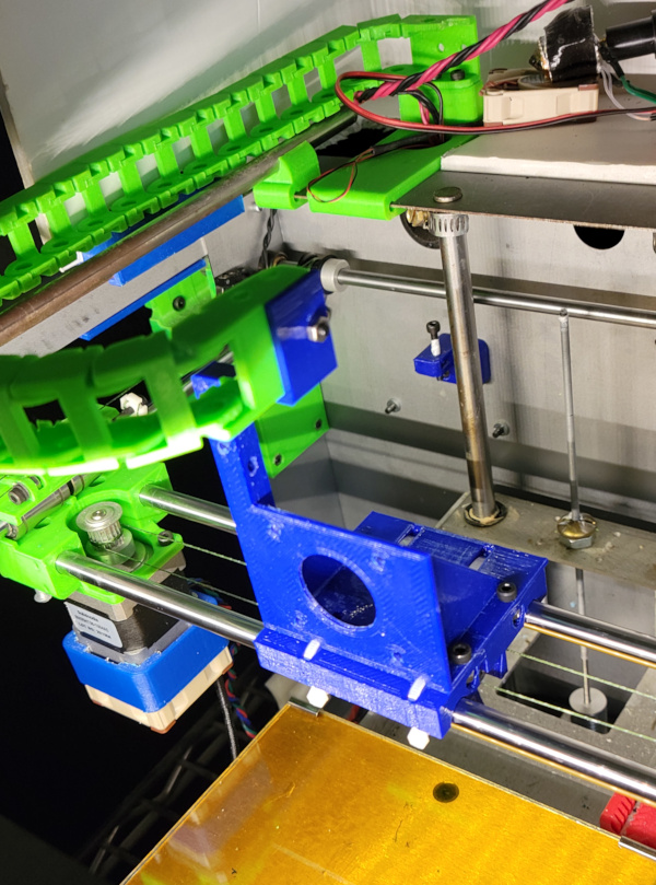
- Cable Chain The bracket I built to holds the areo includes a tower to hold the same cable chain in about the same place.
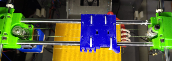
The tip of the nozzle in the Aero is quite close to the rest of the extruder, so the first requirement was a new much thinner carriage allowing the Aero nozzle to reach the print bed. The design I arrived at has channels underneath for attaching and tensioning the fishing line using M3 bolts and nuts dropped into nut traps from the top. Special shape blocks match the shape of the channels and hold the line in the right place (the asymmetric shape prevents it from rotating when you are tightening the line). It also has nut traps on the side to bolt down the bracket that hold the aero. It has slots for running wire ties around the bearings to hold the carriage down and take very little space underneath the carriage. There are slots on the front for mounting things (like the yet to be designed part cooler nozzle). There is a gap where the heater block goes to prevent the carriage melting. Finally there is a little bump that sticks out and hits the X stop switch just before the X carriage would run into the Y carriage.
An earlier carriage version shows the special shaped blocks that hold the fishing line and the channels they fit. You can also see the way the wire ties fit through the carriage.
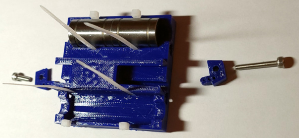
The bracket that holds the aero has holes that match the mounting holes as well as slots where the wire ties live so the bracket can sit flat on the carriage. The face has holes for the motor shaft and mounting screws that hold the aero to the motor (with the bracket sandwiched between them). There is also a tower that sticks up and holds the end of the cable chain.
(The above image is on an earlier incarnation of the X carriage, but you get the idea.)
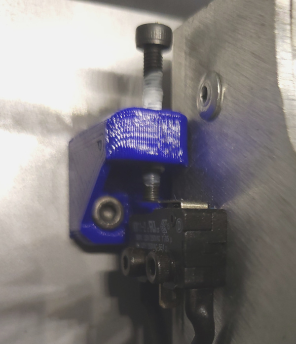
Another part needed to allow the Z carriage to rise high enough was a new holder for the Z stop adjustment screw.
With the Y carriage all the way back, the Z carriage runs into the fan in back of the extruder stepper when raised high enough. I needed the Y stop to be hit earlier to prevent that. Rather than printing a whole new carriage from scratch, I super glued a Y stop extension onto the left Y carriage.

The post sticking out was just a handle to make it easier to glue onto the carriage. I clipped it off after the glue set.
There were, of course, a lot of cables to fool with for the connectors on the Aero, but there is more than one way to deal with those, so it isn't worth describing exactly what I did.
Software
That's it for new printed hardware parts. I also needed to change various things in both the Marlin firmware and the RepetierHost software (which I've always used to run the solidoodle).
Marlin
Here are the changes I made to Configuration.h in Marlin.
--- Configuration.h.orig	2021-08-20 10:50:45.305064814 -0400
+++ Configuration.h	2021-08-24 16:50:26.221890472 -0400
@@ -16,7 +16,7 @@
 // startup. Implementation of an idea by Prof Braino to inform user that any changes made to this
 // build by the user have been successfully uploaded into firmware.
 #define STRING_VERSION_CONFIG_H __DATE__ " " __TIME__ // build date and time
-#define STRING_CONFIG_H_AUTHOR "Adrian/Lawsy/Rincewind/Tealvince" // Who made the changes.
+#define STRING_CONFIG_H_AUTHOR "Adrian/Lawsy/Rincewind/Tealvince/Tom" // Who made the changes.

 // change to 3 for SD3 //{SD Patch}
 #define SOLIDOODLE_VERSION 3 //{SD Patch}
@@ -83,7 +83,7 @@
 // Original Solidoodle w/ Sanguinololu shipped pre June 2013 - Choose 62
 // Solidoodle w/ Printrboard shipped post June 2013 - Choose 81
 #ifndef MOTHERBOARD
-#define MOTHERBOARD 62
+#define MOTHERBOARD 81
 #endif

 // Define this to set a custom name for your generic Mendel,
@@ -143,7 +143,7 @@
 // 110 is Pt100 with 1k pullup (non standard)
 // 70 is 500C thermistor for Pico hot end

-#define TEMP_SENSOR_0 1		//{SD Patch}
+#define TEMP_SENSOR_0 5		//{SD Patch} - Titan Aero SD mod
 #define TEMP_SENSOR_1 -1
 #define TEMP_SENSOR_2 0
 #define TEMP_SENSOR_BED 1	//{SD Patch}
@@ -172,7 +172,7 @@
 // When temperature exceeds max temp, your heater will be switched off.
 // This feature exists to protect your hotend from overheating accidentally, but *NOT* from thermistor short/failure!
 // You should use MINTEMP for thermistor short/failure protection.
-#define HEATER_0_MAXTEMP 230	//{SD Patch}
+#define HEATER_0_MAXTEMP 285	//{SD Patch} - Titan/Aero upgrade
 #define HEATER_1_MAXTEMP 275
 #define HEATER_2_MAXTEMP 275
 #define BED_MAXTEMP 150	//{SD Patch}
@@ -207,9 +207,9 @@
 //    #define  DEFAULT_Kd 114
 //
 // Solidoodle
-    #define  DEFAULT_Kp 15.44
-    #define  DEFAULT_Ki 0.51
-    #define  DEFAULT_Kd 116.62
+    #define  DEFAULT_Kp 21.23   // Titan/Aero
+    #define  DEFAULT_Ki 1.40    // Titan/Aero
+    #define  DEFAULT_Kd 80.68   // Titan/Aero
 //
 // MakerGear
 //    #define  DEFAULT_Kp 7.0
@@ -385,7 +385,7 @@
 #define INVERT_X_DIR false    // for Mendel set to false, for Orca set to true {SD Patch}
 #define INVERT_Y_DIR false    // for Mendel set to true, for Orca set to false
 #define INVERT_Z_DIR false     // for Mendel set to false, for Orca set to true {SD Patch}
-#define INVERT_E0_DIR false   // for direct drive extruder v9 set to true, for geared extruder set to false
+#define INVERT_E0_DIR true     // Sodidoole Titan/Aero conversion
 #define INVERT_E1_DIR false    // for direct drive extruder v9 set to true, for geared extruder set to false
 #define INVERT_E2_DIR false   // for direct drive extruder v9 set to true, for geared extruder set to false

@@ -503,17 +503,17 @@
 #define MANUAL_Z_HOME_POS Z_MIN_POS

 #if SOLIDOODLE_VERSION == 3
-  #define X_MAX_POS 205
+  #define X_MAX_POS 138   // Solidoodle Titan/Aero mod
   #define X_MIN_POS 0
-  #define Y_MAX_POS 200
+  #define Y_MAX_POS 117   // Solidoodle Titan/Aero mod
   #define Y_MIN_POS 0
-  #define Z_MAX_POS 195
+  #define Z_MAX_POS 130   // Solidoodle Titan/Aero mod

 // The position of the homing switches
   //#define BED_CENTER_AT_0_0  // If defined, the center of the bed is at (X=0, Y=0)
 //Manual homing switch locations:
-  #define MANUAL_X_HOME_POS 205
-  #define MANUAL_Y_HOME_POS 200
+  #define MANUAL_X_HOME_POS X_MAX_POS // Solidoodle Titan/Aero mod
+  #define MANUAL_Y_HOME_POS Y_MAX_POS // Solidoodle Titan/Aero mod

 #else //assume SD2
   #define X_MAX_POS 155
@@ -543,7 +543,7 @@

 // default settings

-#define DEFAULT_AXIS_STEPS_PER_UNIT   {88,88,2268,138}  // default steps per unit for Ultimaker {SD Patch}
+#define DEFAULT_AXIS_STEPS_PER_UNIT   {88.70,89.44,6400.00,427.47}  // default steps per unit for Ultimaker {SD Patch}
 //#define AXIS_STEPS_NEGATIVE           {88,88,2268,138} // Step values to be used when travelling in the negative direction. Useful for threadless ball screws. Comment out if not needed
 #define DEFAULT_MAX_FEEDRATE          {500, 500, 5, 45}    // (mm/sec) {SD Patch}
 #define DEFAULT_MAX_ACCELERATION      {1200,1200,100,10000}    // X, Y, Z, E maximum start speed for accelerated moves. E default values are good for skeinforge 40+, for older versions raise them a lot. {SD Patch}
Some of these were just for convenience (because I kept forgetting to fix the eeprom after loading new firmware), others are quite important.
- TEMP_SENSOR_0 5 sets the correct kind for the hot end thermistor.
- HEATER_0_MAXTEMP 285 allows the hot end to get hotter.
- INVERT_E0_DIR true tells Marlin to run the extruder in the opposite direction since the Titan Aero is geared.
- [XYZ]_MAX_POS settings are important to agree with the RepetierHost printer definition or Marlin and RepetierHost will have completely different ideas about where the nozzle is after hitting the endstops.
I used an AVRISP mkII to load new firmware, and it no longer worked on the latest linux systems. I had to update the firmware on the ISP itself before it would work the same way it used to the last time I used it.
RepetierHost
A few tabs need to change in the Printer Settings dialog in RepetierHost.
- In the Printer tab, change the Park Position settings or horrible things will happen at the end of a print (you need not ask how I know).
- In the Printer Shape tab define the
same shape Marlin was told about. The numbers I used (after
checking to see where I could move without running into anything)
are:
- Home X 138
- Home Y 117
- Home Z 0
- X Min -8
- X Max 138
- Bed Left 8
- Y Min 0
- Y Max 117
- Bed Front 0
- Print Area Width 130
- Print Area Depth 117
- Print Area Height 130
- In the Scripts tab check for any custom code moving to the wrong spot.
The X Min setting is a little weird to me because my brain works backward from the way RepetierHost is set up, but basically the X Max of 138 leaves the nozzle 8mm off the right edge of the print bed, and this combination is required to inform RepetierHost of that fact.
I picked a print height of 130 because I usually have a lot of junk in the bottom of the solidoodle and didn't want to crash into it. If it was clean, I could lower the bed more and print taller things.
Note that none of these changes will take place while connected to the printer, so disconnect, make the changes, then reconnect if you want them to work.
That's pretty much it. After all these changes it "works". Just need to get lots of settings dialed it so it works better.
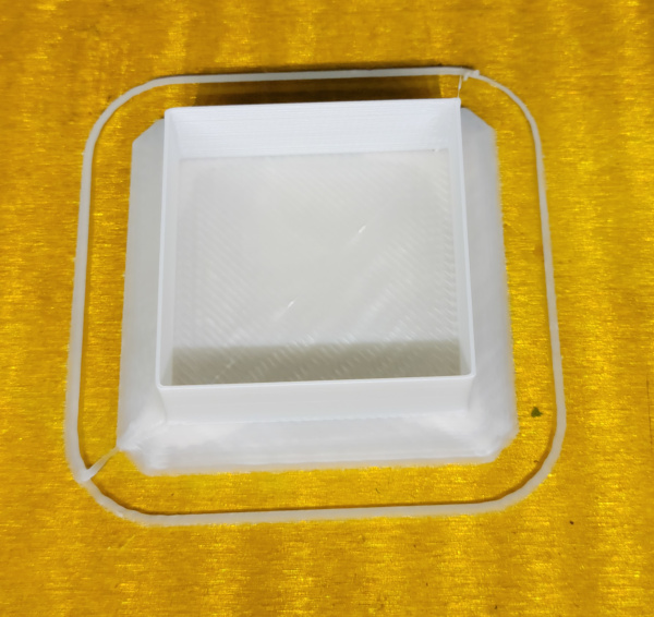
Leveled the bed, got rid of the outrageous retraction settings left from the original configuration, and this thing can print pretty well:
I'm now working on calibration for the new extruder. Also working on adding a part cooler.
Go back to my main Solidoodle page.