Cable Chain
If I'm going to install my E3D someday, I'm going to need to run new cables and perhaps this cable chain can make that easier.
As near as I can tell, this cable chain on thingiverse is one of the more popular versions of a cable chain with lots of makes. I'm hoping this means it has worked well for a lot of people, because that's the model I'm starting with to try and make an even spiffier chain to use on my Solidoodle.
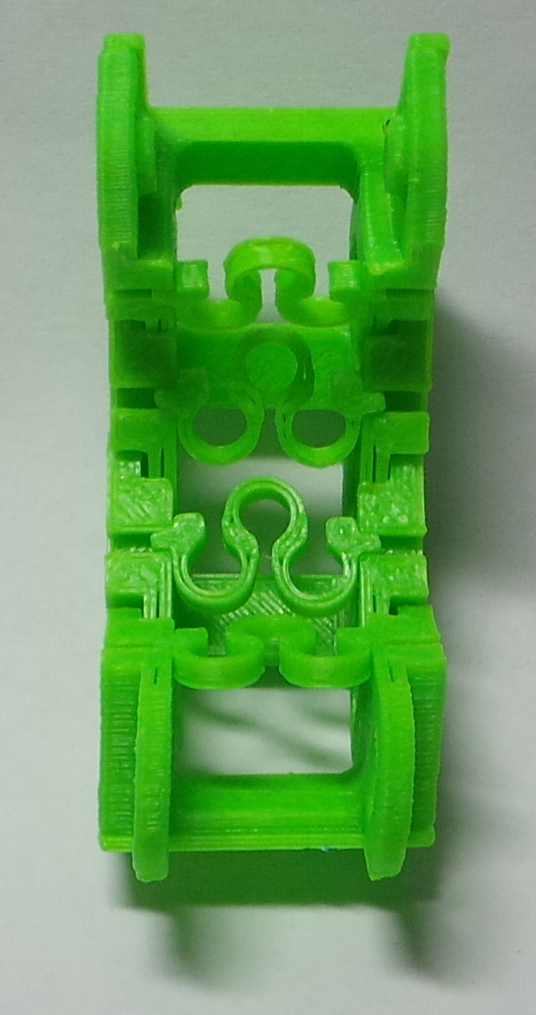
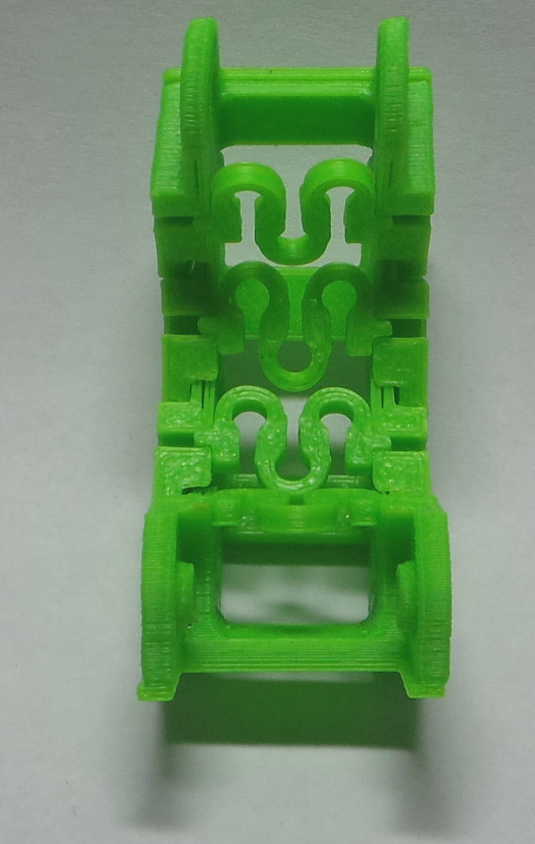
I'm changing the design a bit to remove the top bar. Instead I'm replacing it with 1.75mm holes in the center of where the top bar used to be. The idea is that I can insert bits of filament through the hole, and cut it after gluing it in place. This will give me a cable chain where I can add and remove new cables without having to thread them through from one end. At least that is the theory I'm testing...
My changes are available on thingiverse as Open Cable Chain.
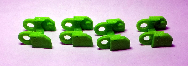
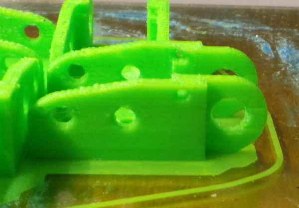
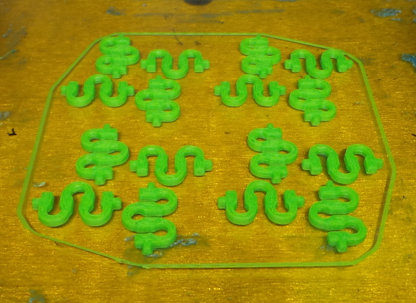
The chain links seem to print moderately well in groups of 4 with no brim:
It does look like there is some sort of retraction problem though. This is the first "real" thing I've tried to print since switching to the new carriage and extruder, and I have no idea why that would need a change to retraction, but it sure looks like it does. The far side of holes seem to print with gaps as if there was too much retraction when it moved over the hole.
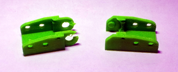
Due to this, or perhaps the lack of a cooling fan (or both), the end piece with the big holes broke off a gap:
I'll try printing 4 of them at the same time so the layers will get cooled off a bit before it comes back to work on each hole again and I'll try it with no retraction at all just for fun:
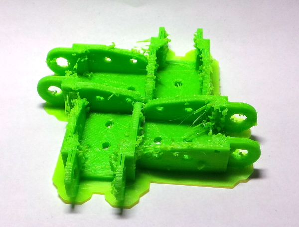
That is impressively hairy :-), but it does look like the gaps following holes are gone, so there must be a better retraction setting I could use. The default retraction it was using before was 2.5, so let's cut that in half and see what I get.
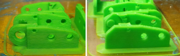
Definitely better, but my internal model of a solidoodle is failing me. I can't explain what causes this stuff:
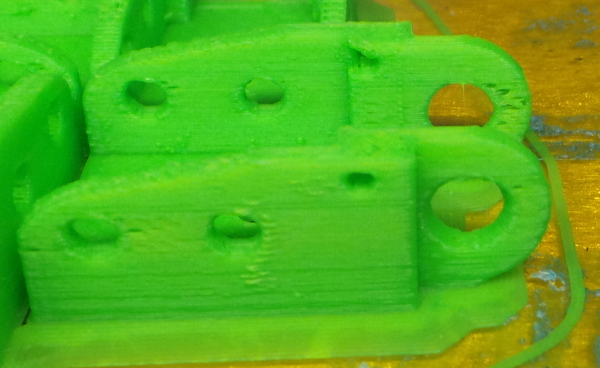
That part is aligned longways in the X direction, and I get swiss cheese following gaps where holes printed. Contrast that to this identical part printed at the same time, but aligned along Y:
I can't visualize what flaw might be responsible for printing worse with part aligned in one direction versus another.
I did wonder if the nozzle might be rocking in the mount a bit, and if it only rocked in one direction, that might explain the difference between X and Y. This Modified Accessory Mount from thingiverse might be a quick way to find out if a rocking hot end really is the problem, so I'm taking a diversion to print one of them before I try the cable chain again.
Nah, the trick accessory mount didn't help at all, the rocking was actually worse with it, but some aluminum foil wrapped around the top of the hot end before inserting it into the mount does seem to have done the trick. I also tightened down the long bolts that hold the extruder to the carriage. There no longer seems to be any rocking at all, so let's print the cable chain end pieces one more time with the default retraction again to see if the hot end rocking was indeed the only problem.
That seems to have fixed it:
I still have no idea what mechanism causes the swiss cheese effect only after gaps in the print, but it is clearly better now. I also note that the sides of the prints are smoother with minimal lines showing up at random levels. Perhaps I am now fully functional after the carriage swap.
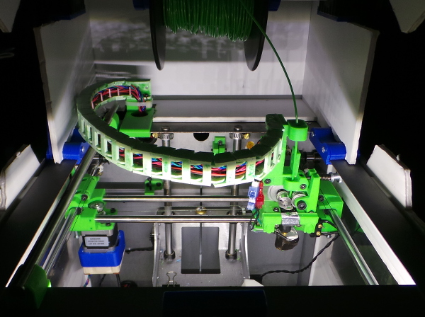
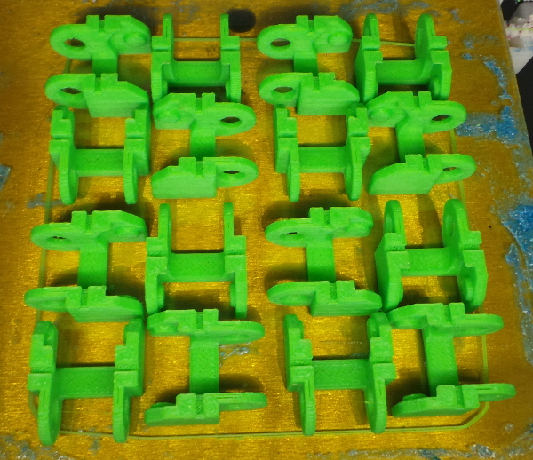
Time to print a slew of chain links with the improved carriage stability. An array of 16 will take a while, so I leave it printing overnight, and in the morning, I get:
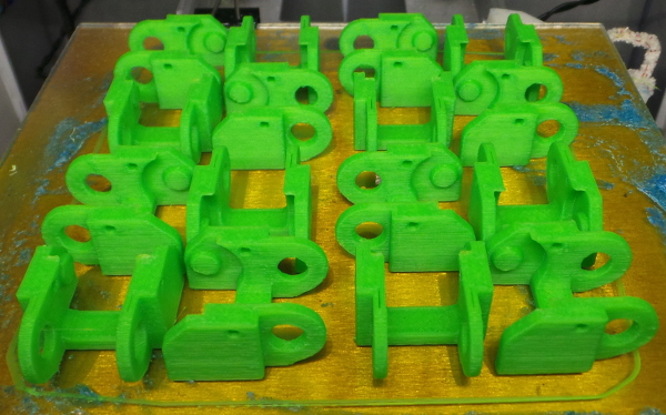
Amazing! Nothing went wrong when I left it alone :-).
Now I need to plan a way to hook it up (and probably print another 16 links). Since my case has loads of room in the top, I'm thinking it will be best if I go up and over the back of the printer rather than through the hole. Over the top will give the chain plenty of room to roam without hitting anything. I just need to devise a way to mount it that high.
Meanwhile, I've inserted nice festive red filament in all the holes (I am working on this over Christmas holiday, after all), dipped each one in acetone (for strength as well as to glue in the filament) and hung them up to dry:
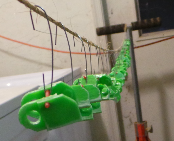
I've noticed a tendency towards slight tackyness with acetone dipped parts, so I'll give them plenty of time before trying to assemble the chain. I can work on how to mount the ends while they get dried out.
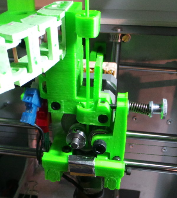
I've got the first test mount built:
I can try mounting one end of the cable chain at various heights and orientations (you can't see them, but the same set of mounting holes run through the bar from side to side as well as front to back) on this bar and find the one that works best when I move the carriage around. Eventually, I'll just want to print a new filament guide with the mount incorporated directly into it. Now I need to devise a matching test mount for the other end.
If I include a second filament guide at the top of the new piece, the filament won't run into the cable chain mount, and I'll also be able to add a place to install a microswitch between the two guides to notice when the filament runs out (yet another cable to run through the chain).
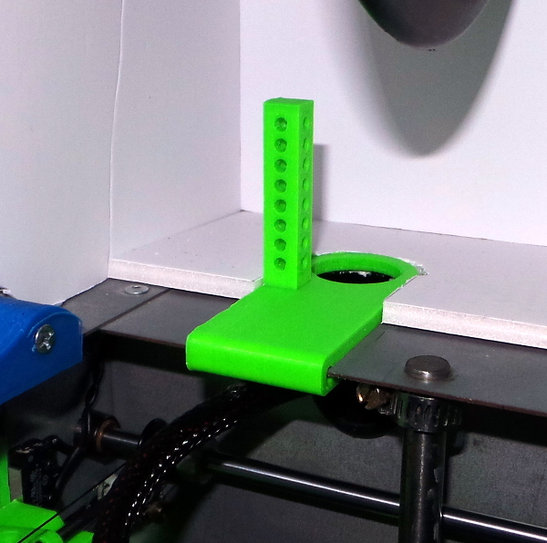
Here is the test mount I devised for the back of the Solidoodle frame (derived from my clip on case parts.)
Only thing left is to finish the chain parts and see if I can figure out what the best length of chain will be and how to attach it to the test mounts. I should be able to do some dry runs of things like printing another array of links to see how the chain moves, and test one link to see if I can insert and remove a cable several times without snapping off the filament. If it all works, I guess it will be time to adapt the test mounts to be permanent mounts and really move all the cables.
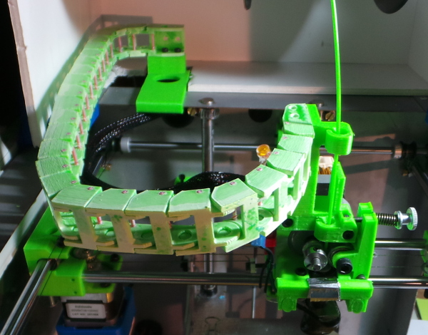
Well, I put together a length of chain and tested some mounting configurations till I found one I liked and did a dry run of the first couple of layers of printing the array of 16 links and it seems to move OK. I'll want to shift the official mount point back a bit on both the case and the extruder and perhaps remove a link or two. It probably wouldn't hurt to make some clip on shields for the chain to slide up on when it gets near the edge, but it is looking like it can drag the chain around with no problem.
I've also played with a couple of links to see how the filament works. Looks like my best bet is cutting a fairly large gap right at the top of the link. The gap nearer the center of the link took very few insertion/removal cycles to snap off. I'll have to mostly hope that gravity keeps the cables on the bottom, and they don't find a way to work out of the gap. (Maybe things would work better with nylon filament, but I don't have any of that, or any idea how to glue it to ABS :-).
I've started to work on the final versions of the mount, and I've come up with something like this for mounting on the extruder in place of the normal filament guide:
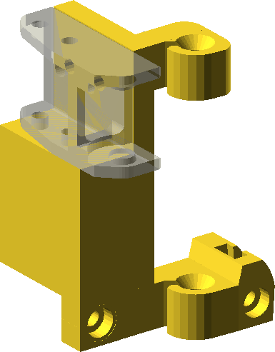
Still need to determine the actual height I should print at and as long as I'm going to print a giant complicated piece (which will obviously need support added), I want to add a place to mount a microswitch to notice when the filament runs out (at least I'll have a place to run the new cables from the microswitch :-).
Well, I finished tweaking the extruder mount and went ahead and let it print overnight while still dragging around the chain on the test mounts:
It seems to have printed OK, and nothing bad happened to the chain:
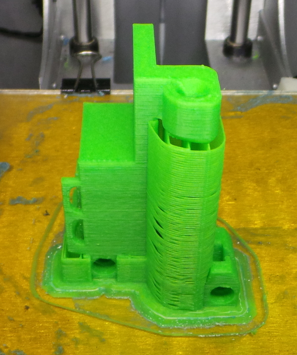
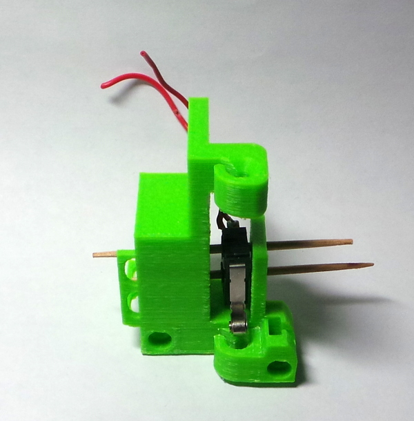
After some time spend hacking past all the support and cleaning up the part, here is the result showing the microswitch in position (with toothpicks in place of the tiny bolts I don't yet have :-).
Now I need to fix up the final version of the mount for the other end of the chain:
Since I needed to use long bolts to attach it, I had to drill out the matching hole on the opposite side so I could drop the bolt straight down.
Next, I guess it is time to cross the Rubicon and remove the kapton tape it says to never remove so I can try mounting the extruder piece. That should allow me to figure out how many links I can remove from the chain while still reaching all parts of the print bed.
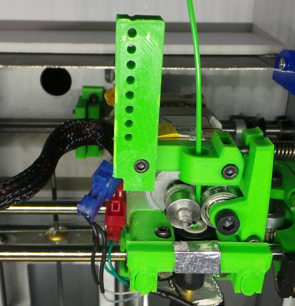
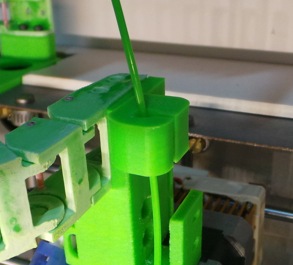
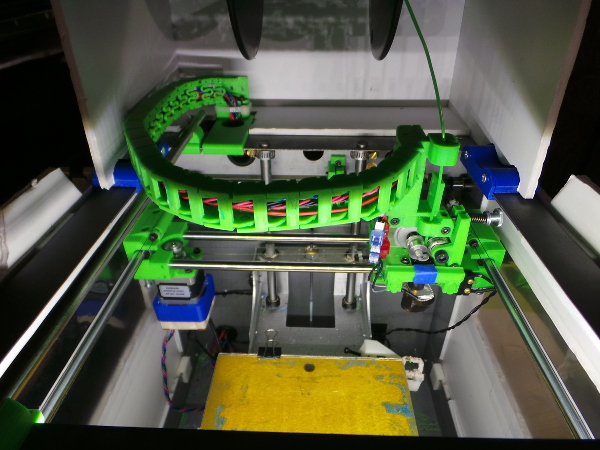
I went and did it, I now have the new extruder mount in place:
I can see one mistake I made was having the slot in the top filament guide line up with the bottom one. Up that high, the filament wants to get tugged out of the slot. It would have been better to rotate the slot around to the front on top. I'm not planning to redesign the part though. I'll just rig up some kind of clip to keep it from coming out of the slot.
The original cable bundle is still there attached with a zip tie. No wires have been moved yet (because I'm pretty sure I'll be soldering extensions on everything when I take the longer path up and over the back :-).
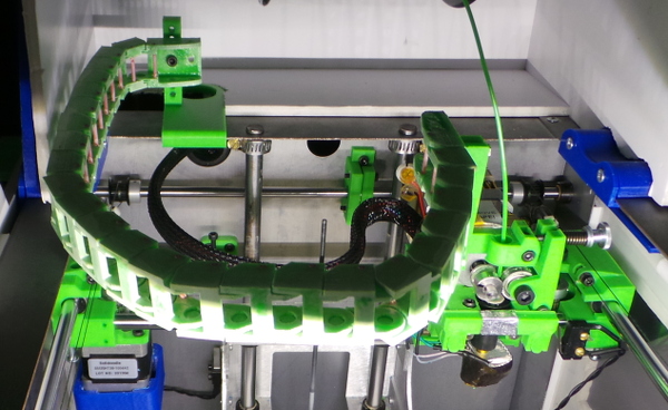
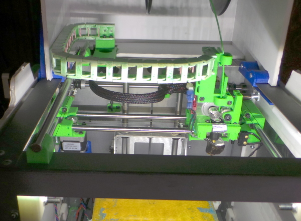
The whole thing looks like:
I'm almost certainly going to need something to let the chain slide up on top of the case when I move left, otherwise it might jam against the edge of the case or other bits like my filament spool mount. Cardboard and tape will probably work till I can print something more elegant :-).
Everything does seem to move around OK, and it looks like I can remove one link and still get to the entire print bed, so that leaves me with a 23 link chain.
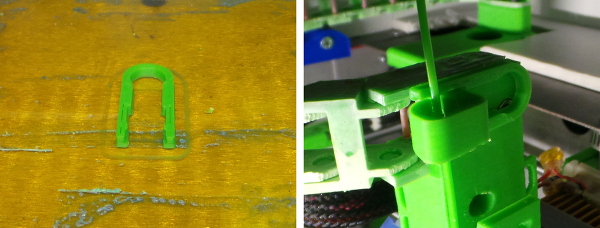
And I can still print things (though I need to calibrate the Z level again after getting things back together - the first layer is too squished). Here's a clip I just printed I'm trying out to compensate for the filament trying to come out of the top guide:
I may actually see about moving the wires to the chain soon. Not much more I can test...
Hey! I thought of a way to avoid moving the wires :-). It occured to me that the 8mm rods leftover from my previous carriage upgrade would make a wonderful rail for the chain to slide on, so I designed a new part and printed up a pair:
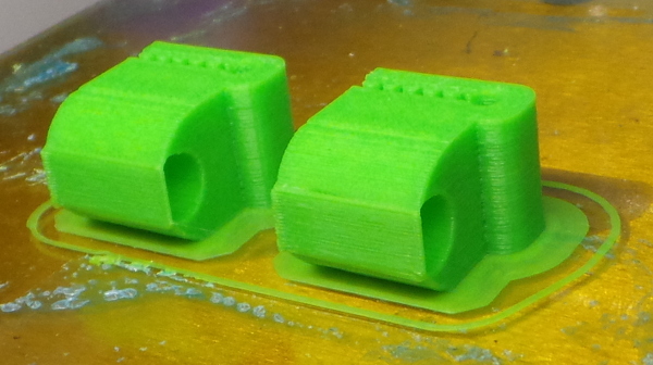
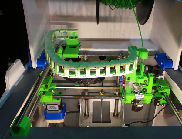
In a tribute to the improved precision with all the mods I have been making, the single wall support I built into the model worked perfectly to allow the clips to print flawlessly. I then got the rail installed in the clips over on the left side:
No more sagging chain!
I've also had a much better idea about how to deal with the top filament guide, so I can work on that design and test printing that new part with the rail in place before I move the wires:
Instead of a clip, a cap to go over the top with a slot on the opposide side so there is no place for the filament to escape.
Put it all together and you get:
Now I really am out of excuses to move the wires...
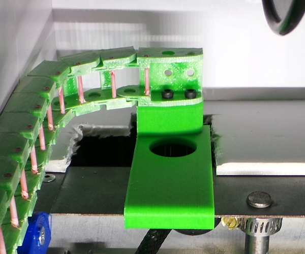
Some small sharp scissors cut away the existing sheath, and I was able to unplug all the cables (taking lots of pictures first) and run them back through the grommit. I then spent some incredibly fiddly time getting the cables over the bits of filament and into the chain. It was not fun, even though I did develop a few skills as I went along like wedging my smallest socket driver behind the filament to support it against pressure while using needle nose pliers to force the wires over the top of the filament. I did manage to break off 3 filaments even being careful, but I think the cables should stay put anyway.
I suspect it would be a lot simpler to just leave the holes and bend some small copper wires through them after shoving the cables in. If I ever replace the chain, I'll try that.
Anyway, two of the cables are indeed too short:
So I'll have to do some soldering to extend the extruder motor cable and the hot end heating element cable before I can get things going again.
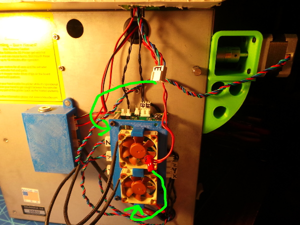
While I was fiddling cables, I moved the LED and extruder motor cooling fan over to my separate 12 Volt power box to take whatever small load they represent off the motherboard.
And after some fiddly soldering of extensions to six wires, it is alive again. Everything seems to function and I can call this finished (for now, but I'd like to come back and invent a better way to run an open chain - maybe print some springy clips to go in the holes which would be less pain than getting the wires over the filament).
When I get my tiny bolts, I should be able to install the microswitch for filament out detection and run yet another set of wires through the chain.
Here is the first print of a calibration cube after getting everything back in one piece:
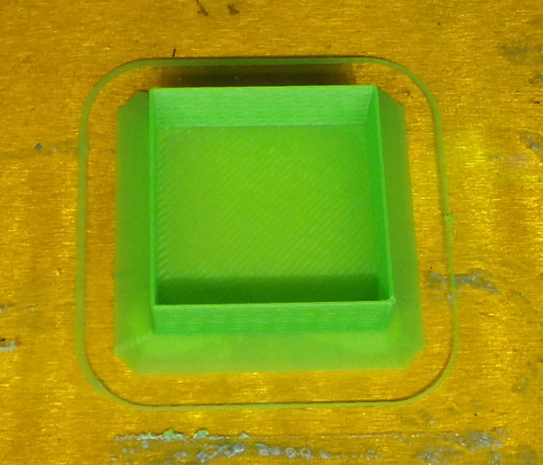
Everything looks water tight, all threads joined up, no evidence of problems dragging the chain around. It is definitely looking good.
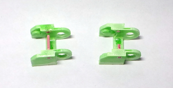
And now, I've been attacking the redesign:
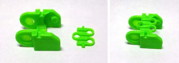
I need to print some more of these and make sure the chain can still move OK with the springy clip in place, but this is looking lots more functional than the bits of filament.
As I suspected, the spring clips are too big. When you try to curl up the chain, the clips run into each other:
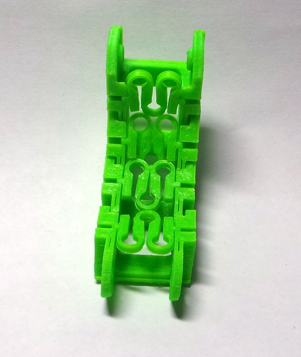
I'll have to tweak the openscad to make them narrower.
No problem with the springs hitting each other now, but they seem a little flimsy. Let's make them just a tad larger and make the wall thickness of the cylindrical sections a little bigger (and a multiple of extrusion width):
That looks to be the best spring yet. They don't collide when curling the chain to the max, but they are quite sturdy. Tugging on them won't get them to come out of the links. Only by pulling down to get the pin out of the slot will they come loose, and that seems to be pretty easy, but isn't the kind of force that will happen naturally in use.
I'm definitely liking this design a lot more than the first cut with the bits of filament.
Here's a collection of links with the new slots instead of holes:
And here is my spring collection:
Now I can break off all the filaments in the old chain, remove it, and replace it with a new chain which should make it infinitely easier to insert the cables:
It was indeed much simpler to insert the springs than to get the cables over the filament, and there is no way for the cables to pop out using the springs.
Update: I've been printing with the chain for a few days now, and no springs have popped out yet. Also I added a new fan to fit the new carriage, and ran the new cable for it through the chain. It wasn't exactly fun, but it wasn't too hard. After getting a little practice, it was fairly easy to just push the top of the clip down (using a dental probe I happened to have), pull the top out, slip the new cable behind the clip, then push the top back in.
Go back to my main Solidoodle page.