X-Axis Stabilizer
I had to remove this mod while converting the solidoodle to use the Titan Aero extruder, but I have now invented a new way to clamp the same bar to the carriage much closer to the carriage so it no longer runs into anything.
This post on the soliforum has a great design for an X-axis stabilizer to keep the bed from vibrating or being shoved back and forth by friction if the print head scrapes a bit. I couldn't see any way to improve it, so I copied it.
Since no .stl files were posted I had to load the free SketchUp Make and install the .stl exporter from the add-ons menu. That allowed me to generate the .stl files from the .skp file in that post.
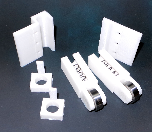
First I printed everything. The large pieces that clamp the rod to the print bed seemed to print best on their side so you wind up printing a tall skinny wall, the other pieces are more obvious how to orient for printing.
The 8mm cylinders that serve as a axles were a little too big and blobby, but wrapping some sandpaper around them and twisting a few times got them to fit tightly in the bearings. Likewise, the holes in the part that holds the bearings were a little small, but wrapping the same sandpaper around a small stick and sanding the inside of the holes a bit made them a nice press fit in there as well. I suspect they would stay together just from the press fit, but a tiny brushing of acetone on either side welded them for sure.
The tongue and grooves needed a bit of sanding as well to fit smoothly without binding (but still tight enough that the parts won't be able to rotate).
I happened to already have a spring assortment from Home Depot, and there were really only two possible choices to select from. One was more tightly wrapped, which wouldn't allow me to compress the spring as much before it was compressed all the way, so I selected the other one that was looser (about 5 turns) and could be compressed more (so more of the aluminum bar could slide into the hole, holding the part straighter).
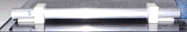
Now I put one end of the rod in a spring loaded hole and push until it feels like there is "enough" resistance. Very subjective, mind you, but that gives me 18mm of rod in the hole. Placing the parts in the bottom of the solidoodle against each wall and measuring the separation gives 148 mm of space between them, but the very bottom of the solidoodle has a lap joint that adds 0.8mm to the wall thickness, so the separation when the mounting is finished will be 149.6mm (not that such exactness is required with everything spring loaded). Anyway, that works out to 18mm on the left, plus 18mm on the right, plus 149.6mm separation, which gives a rod length of 185.6mm. Let's call it 186mm or about 7 5/16 inches.
A little work with a hacksaw and miter box, and I can test fit the pieces:
Next, test fit the tongue pieces, marking where they ought to go so they'll fit in the groove. Scuff up the aluminum surface a bit to insure the glue will hold well. Mix up a little bit of J-B Weld, smear it on the aluminum rod, and add the two tongue pieces. Remove the excess epoxy that oozed out with a cotton swab, and place it on a nice flat surface to cure (this isn't fast set epoxy, so I'll give it overnight).
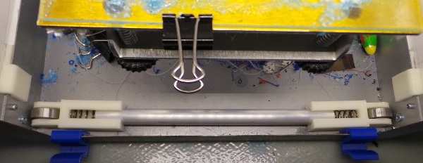
It is tomorrow, the epoxy has cured, time to install this gadget. I first drill out the holes in the large pieces that will clamp the aluminum bar using a 1/8 inch drill bit so the M3 bolts will fit nicely. I then tape 3 M3 nuts to the nut traps on the bottom so they'll stay in the traps when the piece is upside down. I then position the pieces (which is a little tricky since the rod keeps trying to scoot off under the spring force). Once I get all three bolts started, it is easier, since the rod can't go very far. I line things up by eye, make sure the rollers are vertical, then screw the bolts down tight, and I'm done.
The bed seems to go up and down with no problems, and I'll see if it helps with unwanted bed movement and vibration as I get experience with it...
Update: I was able to print some very tall parts for a Sonic Screwdriver after adding this and the PWM Fan Mount, so it definitely seems to have helped.
New Aero compatible mount
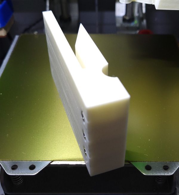
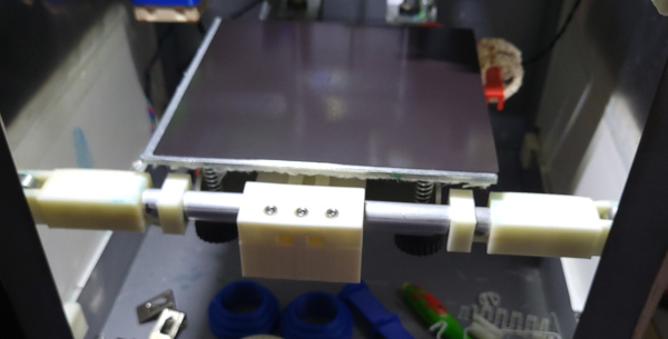
I have a massively over engineered block that slides inside the carriage far enough so the slot for the bar brings it right up against the face of the carriage. Some M3 bolt holes were printed and M3 nuts press fit into the bottom of the holes:
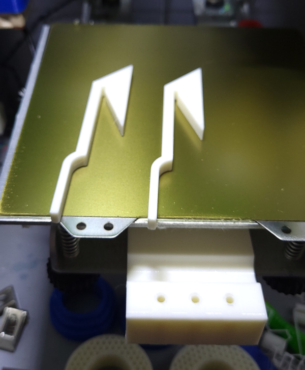
These silly hooks fit under the angle in the back and wedge the block down when pulled forward all the way. Took a few tries to print some that would fit since the insulation sags a bit on the bottom of the heated bed:
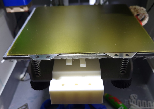
I can insert the block and the hooks, with the hooks shoved back out of the way so I can fit the bar in place:
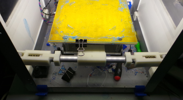
The add the bar and pull the hooks forward:
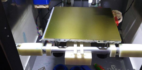
Finally attach the last part and screw down the mounting bolts to secure the bar and the hooks:
The bearings now run along the innermost edge of the frame and no longer collide with the raised bolt holes on the left side of the front of the frame (which I guess were for attaching hinges if you got the version with a cover which I didn't buy).
Go back to my main Solidoodle page.