Y-Rod Direct Drive
This is available on thingiverse as Solidoodle Direct Y Drive Motor Mount.
The Y Belt Tension gadget improved my circles a lot, but didn't perfect them, and over time, I noticed it dragged the whole Y rod to the left with the somewhat off center force it applied to the belt.
Because things improved so much, it seems obvious that the belt drive is indeed the source of most of the problems, so I am all fired up to totally eliminate the belt and drive the Y rod directly with the motor stuck outside the case.
This needs a longer Y rod, a 5mm to 6mm shaft coupler, and a way to mount the motor outside the case.
Having recently discovered the wonders of Misumi USA, I ordered a bunch of stuff from them. For this particular mod, that includes:
- SFL686ZZ ($7) - a nice new flanged ball bearing to go in the Y Rod support (I noticed the old one was somewhat banged up from all the kludgery it has been through with old and new pillow block).
- MCOCG17-5-6 ($28) - an oldham style shaft coupling to connect the 5mm stepper shaft to the 6mm Y rod. (The most expensive single item, and the one that holds up the shipping the longest, but hopefully is exactly the right sort of coupling to pass all the torsion directly to the Y rod).
- PSFJ6-340 ($12) - a 6mm diameter 340mm long hardened shaft to replace the existing Y rod (this is longer than necessary, but I don't mind a bit extra sticking out as long as there is plenty available to hook up the motor to the coupler).
The tricky bit will be getting good alignment on the Y rod pulleys. Normally you see if there is a tendency to drag the rod left or right, but once the motor is hooked up that can't happen, so I'll probably want to test fit things to find out exactly where the rod needs to sit, then remove the motor while getting the pulleys positioned till I reach the point that the rod doesn't move and is sitting in the position I want, then attach the motor permanently. Hopefully, that will keep most of the force going towards useful motion rather than wasted effort.
While waiting for my parts, I might as well do something about a bracket to hold the motor. The parts at Solidoodle Y-Axis Direct Drive include a bracket, but there is no telling if all the parts will line up the same from one solidoodle to the next, or if my shaft coupler will fit in the same amount of space, etc. I might as well steal some of the ideas, but design my own which I can make adjustable in openscad.
When picking off positions of all the rivets and bushings and wot not on the side of the solidoodle frame, Play-Doh is your friend :-).
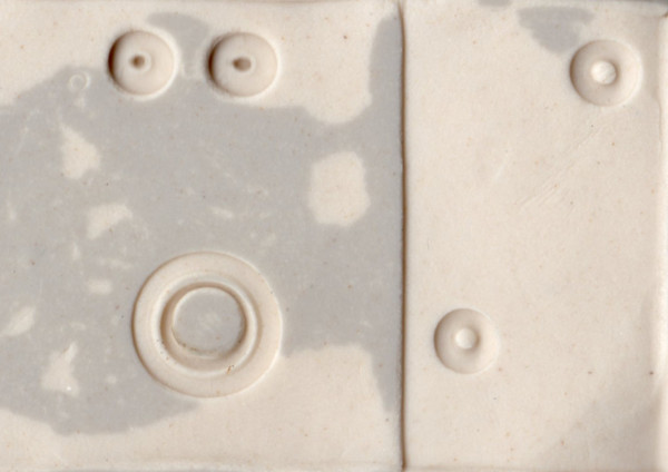
The above is a reduced copy of a flat bed scan of a Play-Doh impression taken of the side of the solidoodle frame at the top around the Y rod bushing.
The original was 600DPI and I was able to pick off the locations of all the features using gimp and recording the positions and size of rectangular selections around each interesting bit. That led to the following bit of kludgery to model the parts in openscad and produce a template I could print to make sure everything actually lines up correctly at the measured positions.
ptmm = 0.04233333;

cylx = 10;

rotate([0,180,0])
difference() {
   cube([1044*ptmm,5+1232*ptmm,6*0.3]);
union() {
// Overlapping metal sheet at top of frame
cube([1044*ptmm,582*ptmm,0.89]);

// Rivets (1.2mm high above sheet)
translate([ptmm*(681+(149/2)), ptmm*(373+(144/2)), 0])
   cylinder(h=cylx+1.2+0.89,r=(153*ptmm)/2,$fn=64);
translate([ptmm*(86+(152/2)), ptmm*(63+(153/2)), 0])
   cylinder(h=cylx+1.2+0.89,r=(153*ptmm)/2,$fn=64);

// Y bar bushing
translate([ptmm*(555+(327/2)),ptmm*(850+(333/2)),0])
   cylinder(h=cylx+1.2,r=(333*ptmm)/2,$fn=64);

// Screw buttons for Y switch
translate([ptmm*(72+(142/2)),ptmm*(862+(148/2)),0])
   cylinder(h=cylx+3,r=(148*ptmm)/2,$fn=64);
translate([ptmm*(67+(145/2)),ptmm*(1090+(142/2)),0])
   cylinder(h=cylx+3,r=(148*ptmm)/2,$fn=64);
}
}
Which results in this printed part that does indeed line up quite well with the junk on the solidoodle frame. So I have the info I need to subtract off the back of the mount so it will sit flush with the frame.
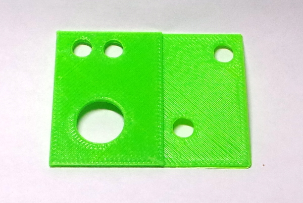
Now all I need is the rest of the mount to subtract it from...
I've started on a file of useful openscad modules to build the mount, and another test print is the "testplate" module. It uses values picked off the motor mount in thing 583132 to check the offsets from the existing motor mount slots in the case to the center of the Y rod. The dimensions I picked off the model do seem to be correct. The test piece lines up properly with the solidoodle case.
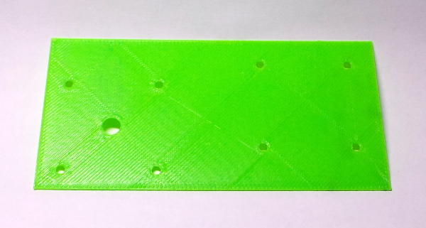
So, I think I have all the solidoodle geometry I need figured out.
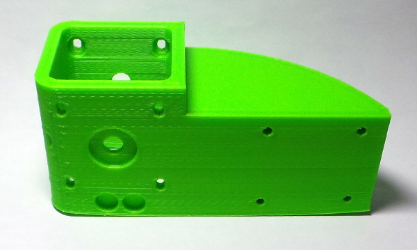
After plugging away for a while with openscad, I produced the final motor mount part, and changed the testplate module to slice the bottom off the full part so I could do a quick print and discover if the final part still kept all the correct dimensions:
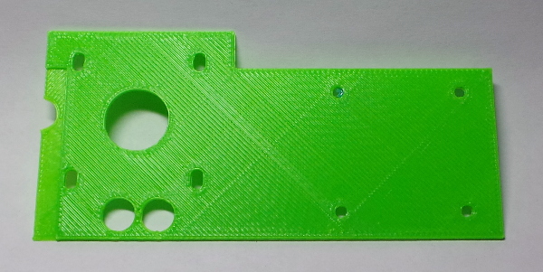
That all matched up perfectly, so I decided to go ahead and print the full mount so I'll have it when my parts arrive. Weirdly, slic3r goes completely berserk when slicing the stl file generated by openscad. I tried running the model through the netfabb online repair service and that not only produced a much smaller file, but also produced a file that sliced OK, so I'm now printing the fixed version.
Unfortunately, printing massive objects is kind of a problem. My first attempt curled up enough to misalign the mounting holes:
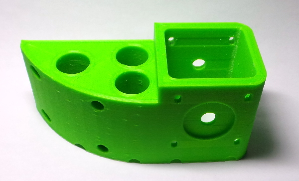
I've revised the model some to run notches across the bottom for strain relief and punch a few holes to make it less massive. It now prints better:
Hopefully the other parts I need will show up soon and I can try installing it...
After fiddling with the model a bit more, I managed to produce an stl file that slic3r likes without having to run it through the repair service (apparently not all the bits were fully joined).
...All the parts have come, so it is time to start taking things apart, which gives me a chance to test fit the motor mount:
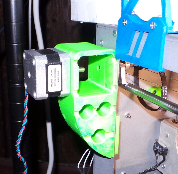
I had to swap in some 20mm M3 bolts to mount the motor since the old mounting bolts are too long (with part of the shaft not threaded) to use from the front face of the motor. I used 10mm bolts to mount the bracket in the old motor slots with the faceplate and nut traps on the inside of the frame. They are just long enough to fully engage the nuts without sticking out.
I may have the motor shaft extending into the bracket a little farther than it ought to, but some washers on the other side can probably fix that if I can't get the coupler to fit (and is a lot faster than putting things back together and printing a new resized version of the bracket :-).
I'll also need to refit my foamboard case on that side, but a little work with a utility knife should handle that (one of the many advantages of using foamboard).
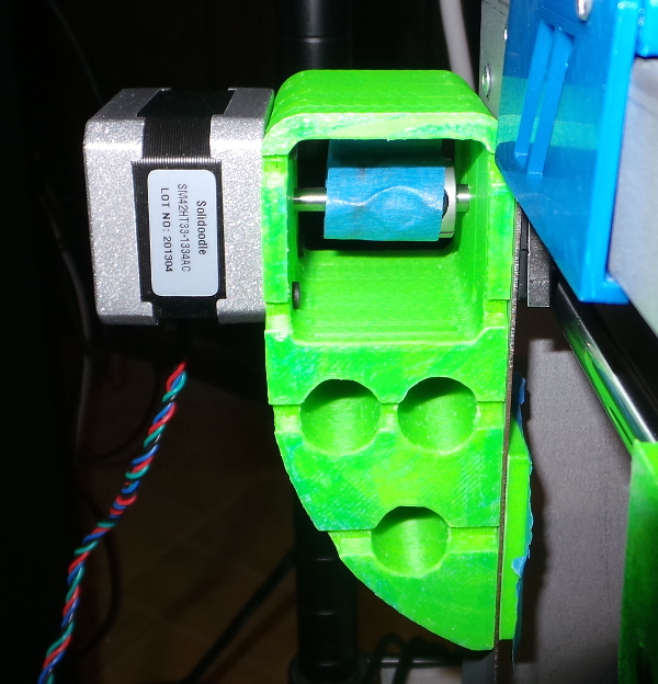
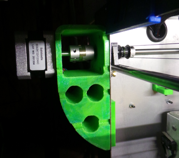
I've gotten to the point where I can test the new Y drive rod, and I've found that the motor won't need any washers. The size of the mount came out perfectly. I've got the oldham coupler test fit to the motor and the rod now (with some tape to keep the three parts of the coupler together) and everything fits well:
On the other side of the printer I've taped a piece of paper I can mark exactly where I want the other end of the Y rod to be when it is all the way into the coupler. This will allow me to take off the motor, install the new fishing line on the left and right and adjust things so +/- Y movement of the carriage leaves the Y rod sitting in the correct location (or maybe allow it to try and slide slightly towards the motor end so it will tend to keep the coupler pieces together :-).

I did find I needed to slide the pulleys a tad to the right so they would tend to drag the rod to the left and keep the coupler parts from separating. That was easier than rigging up some kind of thrust bearing to go on the other end of the Y rod.
One odd thing I found: The old rod would slide through the bushings on the frame with no problems. The new rod slides though from the outside perfectly well, but when I try to go all the way through the other side (no matter which direction I come from), it gets totally stuck just a millimeter or so into the bushing. This had me completely mystified for a while, but I found that if I stuck the old rod in the other side of the bushing and wiggled it around some, it would eventually find a sweet spot that let the new rod slide the rest of the way through. I can only assume the new rod has a sharper edge that digs in if not perfectly aligned. Certainly both the old and the new are exactly 6mm when I measure them.
Meanwhile, I've gotten both this direct drive and the new carriages installed, and it all seems to work!
See the Fun With Cylinders page for an example of how much better cylinders now print. This direct drive thing seems to work pretty well to eliminate backlash!
I may need to add some sort of contraption to keep the Y rod from shifting. I printed lots and lots of stuff, but last night the Y rod apparently decided to suddenly shift right for some reason and popped out of the oldham coupler, making it hard to move in Y :-). I guess I'll keep track of how often this happens here:
- Jan 7, 2015
- Dec 9, 2020
Six months later, and the coupler hasn't ever come apart again. I've printed hours and hours since then making (among other things) the parts for Jiggit (the core XY printer I'm building). I guess this one time was just a fluke.
OK, it finally popped loose again 5 years after the first time. That doesn't seem too dreadful.
Yikes! It has come loose a couple of more times recently, leading me to develop yet another mod: Y-Rod Shaft Stop.
Go back to my main Solidoodle page.