Fishing Line Conversion
This Beltless Drive X-Y Axis post on soliforum describes how to replace the belts with fishing line and pretty much eliminate backlash, making movement more accurate.
I have Sufix 832 80lb test braided fishing line.
I printed a few of the special washers for helping to attach the line.
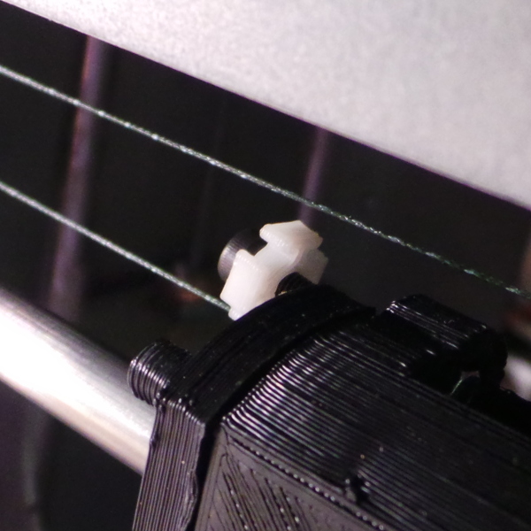
After much fiddly line winding, I got the left side done and it seems to work:
I worked out some techniques while doing one side that should make the second side simpler. The best idea was using a hemostat clamp to grab the line and dangle from the pulley, holding the previously wrapped line in place while feeding the line around for the next wrap.
The right side did go easier after the practice on the left (not to mention that the right side doesn't have a big old X motor getting in the way).
I couldn't see any reason to do multiple wraps around the idler pulleys, so I just looped the line around them without making any extra wraps. It seems to work fine.
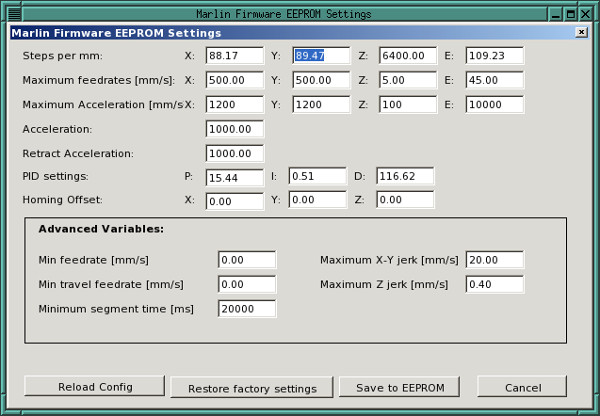
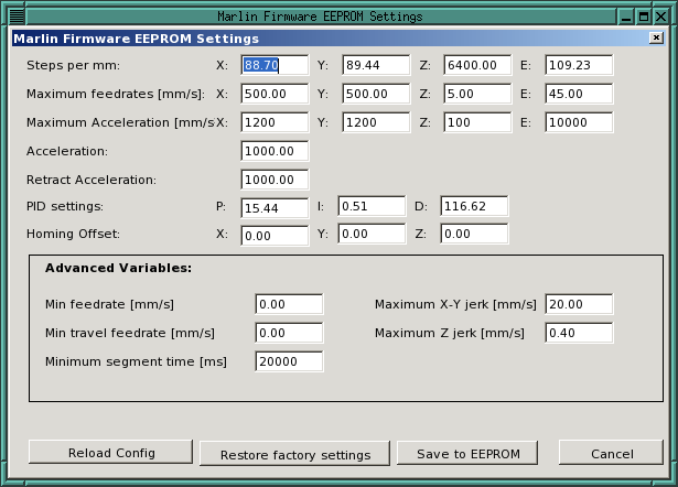
I printed a calibration cube, and found that the Y direction was now printing too short, so I fiddled with the eeprom settings to increase steps per millimeter for Y.
I didn't try to replace the X belt with fishing line yet because I couldn't see how the heck things were hooked up (but see below where I took some pictures that finally led me to believe it is possible, just not today :-).
My calibration cubes look like I also messed up the bed level while I was doing all this work, so I need to recalibrate some things before I print anything important.
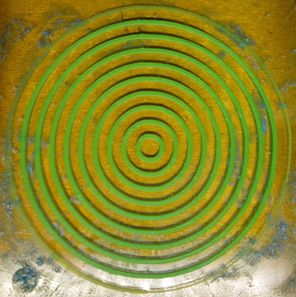
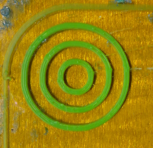
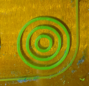
I think I got most things reset correctly, so I tried printing some circles:
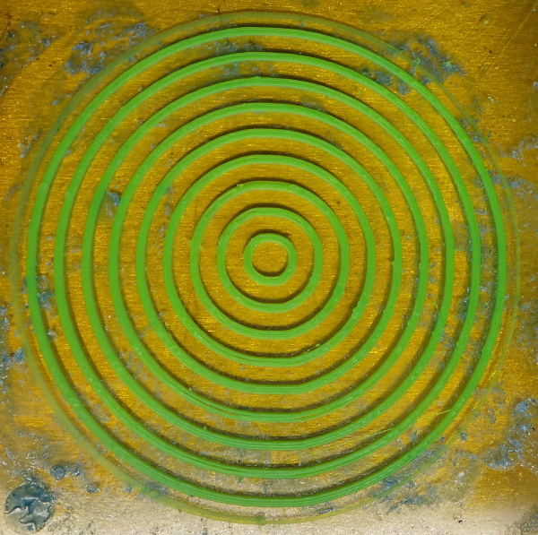
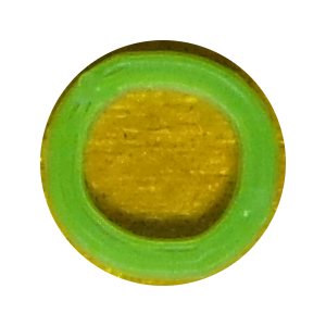
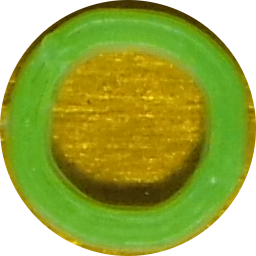
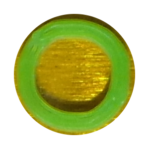
They clearly aren't perfect, if I blow up the smallest circle and do a circular selection in the image, the non-circular bits become fairly obvious:
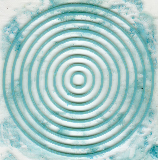
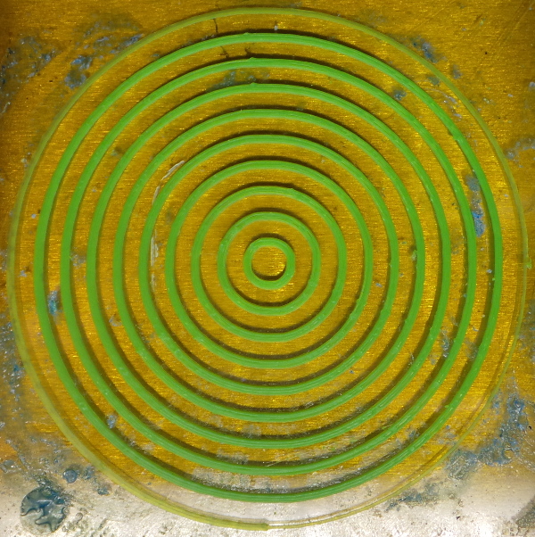
In fact, they seem to have very similar imperfections to some circles I printed before I made this change (this was the glass bed being scanned in a flatbed scanner rather than a photograph):
On the good side, I clearly didn't make anything worse, and I've just gotten it put back together, so I'll see if additional tweaks can make things better (like getting the X belt replaced with fishing line, and retensioning after using it for a few days).
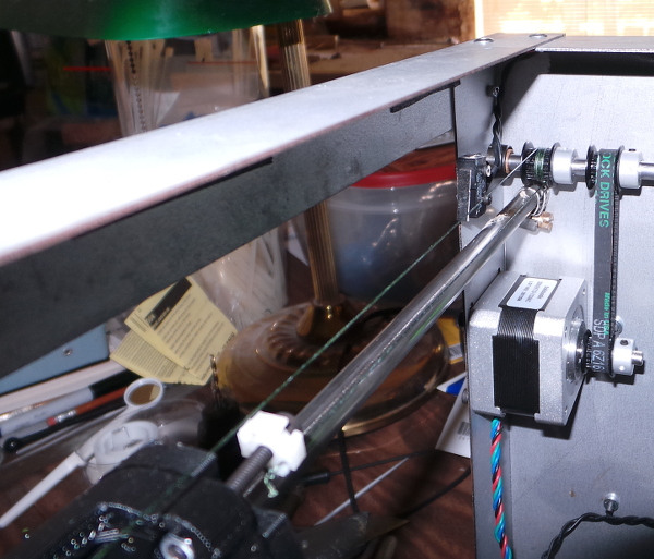
Speaking of the X belt. Here is a blow up of the left side belt connection:
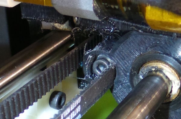
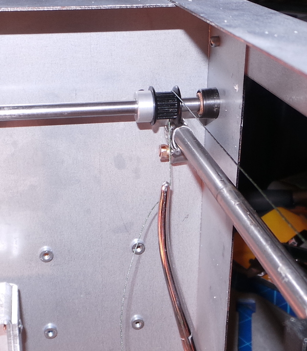
And the (more confusing) right side:
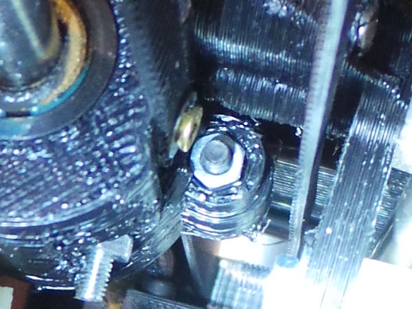
Until I zoomed in on these photos, I couldn't see that the right side is attached to a screw that goes into the barrel of the carriage, but if the small amount of bolt end sticking out of this side next to the screw is any indication, I'll still need a longer bolt to be able to get the washer on the left side and have room to work (unless maybe the bolt end I see on this side is some completely different bolt).
At least I'm starting to see it is possible to replace the X belt.
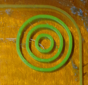
A few days have passed, and I spent some time fiddling with the tension and positioning of the pulleys so the rod wouldn't try to move sideways so much, and I printed a new set of circles:
I don't think there is much different. Here's the smallest:
| Old | New |
|---|---|
|
 |
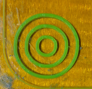
Now, I've added a clamp mod to keep the bearing in the pillow block (possibly silly) and I've printed some more circles with the clamp in place:
Again, not much different for the smaller circles:
| Previous | Newest |
|---|---|
|
 |
I was curious if the position on the bed matters, so I made a new test with 4 separate groups of circles:
 |
 |
 |
 |
Can't say that I detect any real difference, but I think I'm starting to go circle blind :-).
After using fishing line for a while, I decided I had too many wraps around the drive pulleys (3 seems to be enough), and I also wanted to install a better Y bearing and convert the X axis to fishing line. This meant taking everything apart again which gave me a chance to be more careful about how I adjusted things.
I removed all the existing line, then replaced the X belt first. I needed a much longer bolt to hold the washer and give me room to tie the line, but fortunately I had some long M3 bolts.
After getting the X line installed, I did the right side of the Y drive, using just 3 wraps around the drive pulley. I also spent some time dragging the carriage back and forth in Y and watching for the Y rod being tugged sideways. Since the right side was the only side hooked up (all the tension was off the drive belt), that meant that any sideways force was strictly due to the position of the right pulley on the rod. I adjusted the position a bit at a time till the rod no longer moved sideways, thus insuring that the pulley was lined up opposite the right side idler.
I then installed the left side line much the same way. In this case, since I knew the right pulley was lined up correctly, any tendency to drag the rod left or right should be entirely due to the position of the left pulley, so I tweaked it till once again the rod no longer tried to shift left or right.
It was then time to put the belt back on the drive motor and apply a bit of tension to make sure it wasn't trying to drag the rod left or right when moving in Y. Once I got the drive pulley in the right place on the rod, it was time to take the belt off again to relieve pressure on the rod and go ahead and bolt down the Y bearing.
Then I could hook back up the drive belt for real and proceed to do some testing.
This is when I discovered I still had backlash, but the Y Belt Tension gadget came to the rescue. After installing it I seem to be able to print pretty precisely for the first time ever (not that it was useless before, but I never thought it was as accurate as it ought to be).
I printed a few cubes to check dimensions and adjusted the X and Y steps per millimeter values to take the changes due to fishing line into account:
Go back to my main Solidoodle page.