Z-Axis Replacement
I think I screwed up my stock Z-axis thread slightly when my algorithm ran away a few times when experimenting with my Bed Level Sensor. I always have a layer at about 4 or 5 mm that seems squashed too much like the thread didn't move up far enough. So, for my first destructive mod to my solidoodle, I'm planning to replace my giant stock 5/16-18 Z-axis with a tiny flexible M3 Z-axis instead. This will also have the advantage of giving me a finer thread for finer Z movement control.
Most everything here is adapted from this thread and this thread on the soliforum. I also found some threads like this one about drilling centered holes through bolts and adapted it for some tools I had on hand.
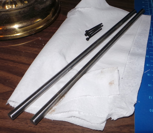
I ordered a 5mm to 3mm shaft coupling from amazon via China, so who know how many weeks it will sit in customs before it shows up. I also ordered a 3MM rod which I did get (from South Carolina, not China) it was slightly bent in shipping, but still has enough straight bits for cutting off the length I need for a Z-axis. I also got a collection of bolts and nuts I ordered, including a few 5/16-18 brass machine screws.
My first step is to try an drill a 2.5mm hole dead center through one of the 5/16-18 brass screws. If I can do that, I'll be able to tap it for an M3 thread, then when I remove the stock Z-axis I can screw the bolt into the existing nut, and adapt the bed for an M3 rod without a lot of effort. A relatively long threaded bolt (compared to an M3 nut) will give me lots of thread to average movement over, so sould be quite accurate (at least that is my current hope :-).
I had a small hobby lathe/drill press machine a long time ago which eventually broke down, but I still have lots of useful parts from it, including a T slotted milling table and a chuck with screw threads on the base that hold a T bolt, so I can fit the chuck to the table and have it pointing straight up.
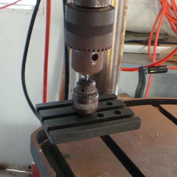
This leads me to try and align the chuck on the table with the chuck on my drill press by clamping a 1/4 inch drill in both of them and lowering it down so I can clamp the bottom piece to the drill press table.
Step 1:
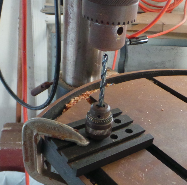
Step 2:
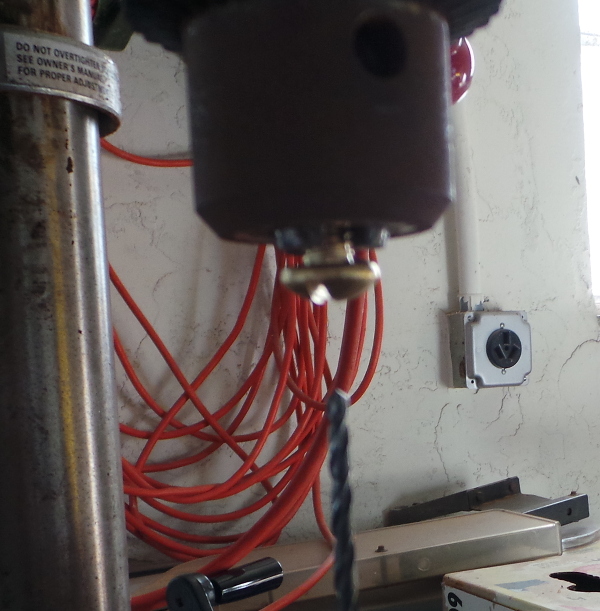
Step 3:
After swapping in the 3/32 drill bit and drilling the hole (slowly), here are the results:
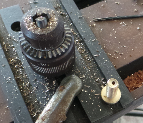
Did get it all the way through, but not too successful. I think I'll need a more accurate alignment of the chucks. The clamping and lowering thing doesn't seem to work that well. I also had a great deal of problems getting the bolt in the drill press chuck actually centered. I think I should insert a 5/16 drill first to get the chuck set to almost the diameter, then I can get the bolt in place without wedging it between two of the chuck bits rather than in the center.
Of course my biggest problem is that I don't have the proper size 2.5mm metric drill, so I'm using 3/32 to work on my technique while waiting for my metric drill set.
Hmmm... I tried a completely different way to align the chucks with an identically off center result. I think my drill press bed isn't really totally square. I'll have to see if I can beg the use of the lathe we have at work (which is probably in better alignment :-). [And one of these days I need to see about tweaking the drill press into better alignment.]
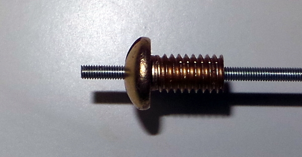
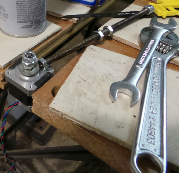
OK, I got a professional at work to drill a nice centered hole for me, and then I was able to use the dremel to cutoff about 1/4 inch so I could run the 3mm tap all the way through it, leaving me with this nice bolt I'll be able to use in the existing nut to provide a 3mm thread for the 3mm Z-axis:
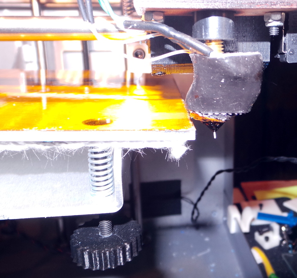
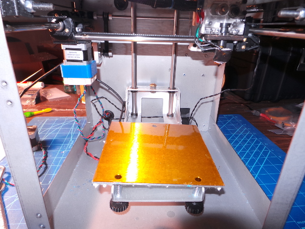
The next problem turns out to be getting the print bed assembly off of the existing Z axis. I can't just raise the bed far enough without hitting the nozzle:
I still have this much thread left:
This wouldn't be a problem if I hadn't epoxied the thumbwheels to the bottom of the bed leveling screws. I could just take off the aluminum plate and there would be plenty of room, but now I have to figure out a different way. Maybe if I take off the Y idler bracket I could move the carriage far enough forward (I've printed new brackets that are stronger, so this would be a good time to put them in). Or perhaps remove the Z axis rods so I can tilt everything forward to get the last bit of the thread out of the nut. Or maybe just see if I can get the thumbwheels off the leveling screws (perhaps by cutting the screws and getting replacements).
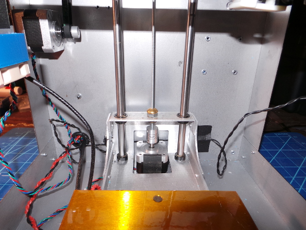
I decided to take out the Z rods since that seemed like the simplest thing to do, and it seems to have worked:
Then I cranked a lot of nuts down the 5/16 rod to force it off the stepper (made a lot of nice creeking hinge noises, but wasn't too hard to force off):
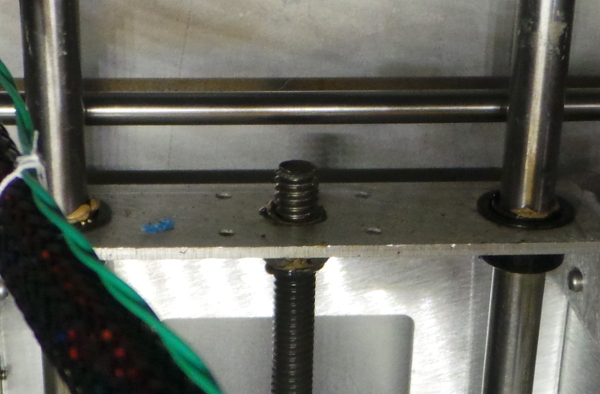
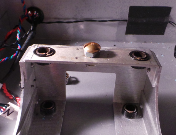
I screwed the 5/16 bolt that has the M3 threaded hole down where the 5/16 rod used to go:
I then carefully put the pipe clamps back in place (one pair under the print bed, one on top) and inserted the rods back through the holes and turned the unit on its side so I could tighten the pipe clamps without gravity making the rods slide too far:
Then I put the stepper back after putting on the shaft coupler:
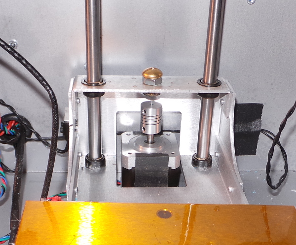
And finally measured the M3 rod against the old 5/16 rod by comparing it to the mark on the motor shaft where the bottom of the 5/16 rod was. I cut off a piece of M3 rod the right length, screwed the newly cut segment down through the hole in the bolt and into the shaft coupler:
Added lots of lithium grease to the thread and 8mm rods, Hooked back up the stepper, set the steps per mm to 6400 in the eeprom, and it seems to move up and down just fine.
I've gotten the bed leveled and the Z-stop set and have been using this for a while now, and it is working fine. The line that always appeared at the same layer in prints is indeed gone, so I think this was a success.
Hmmmm... I just printed a tall part and it came out too tall. It was supposed to be 90mm, and is closer to 100mm, so I need to investigate. Maybe this wasn't as successful a modification as I thought...
Go back to my main Solidoodle page.