New Carriages
The Solidoodle Replacement Carriages on thingiverse are very nice, and the main feature they add is putting both X and Y motion on linear bearings. No more rocking extruders and klunky teflon blocks.
I will also be able to get rid of the Solidoodle Springloader which should no longer be necessary (and won't have a place to mount in any case :-).
Having recently discovered the wonders of Misumi USA, I ordered a bunch of stuff from them. For this particular mod, that includes:
- 8 LMU8 ($47) - linear bearings for carriages to slide on.
- 2 PSFJ8-320 ($24) - new 8mm x 320mm rods for Y motion.
- 2 PSFJ8-280 ($20) - new 8mm x 280mm rods for X motion.
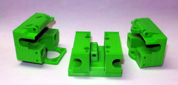
(The new Y rods are probably not strictly necessary, but I have noticed a few patches of rust on the existing rods, so I figured I might as well upgrade them while I was at it.) While waiting for parts, I've printed the new carriage pieces:
Once this works, I'll have to do something about getting the PWM cooling fan hooked up again (and I'll want to make sure I include the fan cable as well as an extra cable for the E3D cooler when I'm putting together the wire bundle).
...All the parts arrived, I got everything taken apart, then I hit the first hitch: I don't have any 50mm M3 bolts. My solidoodle carriage was the variation with 4-40 bolts instead of M3. I guess I can use the 4-40 temporarily then replace them someday when I can get some real 50mm M3 bolts. On the other hand, I tested the 4-40 bolts, and they don't actually rattle around in the M3 sized holes very much, so just going with 4-40 might be OK (fortunately, I have some 4-40 nuts).
ACK! The 4-40 nuts are too big for the nut traps in the middle of the top carriage. I can't use the 4-40 bolts. If I want to get everything put together this weekend, I guess I'll have to improvise a couple of really long "bolts" from pieces I cut off the leftover M3 rod I bought for the Z Axis Mod. (Or maybe I'll drive down to Broward Bolt on Monday morning).
Reading over the instructions, and taking into account that I'm using fishing lines, not belts, I thought the first step would be to make sure I can get the line attached to everything. The underside of the carriage will be especially inaccessible when I put things together, so I've pre-attached a length of fishing line to the right side with a short 10mm M3 bolt and a long 35mm M3 bolt on the left with the special washer to provide a place to tie the other end of the line after getting it wrapped around the drive pulley.
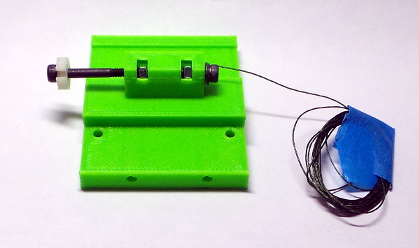
I used a couple of little fiber washers on either side of the line I tied to the short bolt so they could help clamp it in place without being hard enough to wear through the line over time (at least that's my theory :-).
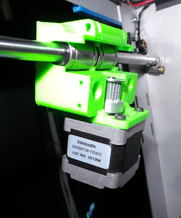
Yikes! Another hitch: The screws that hold the X motor to the left carriage are too long (8mm M3). The old left carriage is thicker, and didn't recess the heads of the cap screws, and the thread doesn't go down very far into the motor. I went and got the shortest screws I could find (6mm M3) as well as a bunch of M3 washers to use under the carriage if the short screws still aren't short enough.
...Fortunately, the 6mm screws work perfectly:
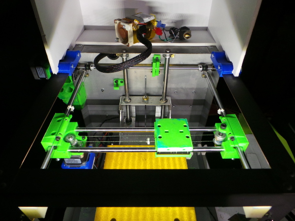
I also installed the new Y rods, which were actually a centimeter or so longer than the old ones, so I stuck all the excess out the back so the cover wouldn't run into any Y rod poking out the front.
The linear bearings slide very nicely, none of the grinding I've read about from other people's experiences.
Next hitch: The screw holes intended for the set screws to hold the X rods in place seem to be too big for a M3 screw to be used to actually hold anything (at least that's the way it printed for me). I guess I can find some short 6-32 screws or something a little bigger than M3. (I used 6-32 which seem to work fine, though I'd like to find some shorter 6-32 screws someday).
After insanely painful fiddling around, I finally got the fishing line on the X drive. I definitely learned that I should have come up with some way to wedge the M3 nut into place before I started trying to get the line exactly the right tension. The magic washers are nice, but once I get close to having the line tight, a single turn around one of the washer arms requires more slack than I can get without completely removing the screw (at which point, the nut falls out :-). Things should be much easier on the left and right Y carriages since the nuts will be held in place by gravity when working on them.
I decided to loosen the X rod set screws while tightening the fishing line on the theory that would tend to pull the left and right carriages together a bit and make the linear bearings more snug in their mountings. I tightened them again after finishing the fishing line.
I've now finished getting all the fishing line and the direct drive installed, and everything seems to work (though it only worked after I plugged the hot end back in — apparently Marlin doesn't like for it to be disconnected.)
On to the new extruder (which isn't strictly part of the new carriage, but I can't do much without also swapping in the new extruder).
Can't print anything till I get some 50mm M3 bolts to install the new extruder assembly, but movement seems to work in all directions when I test it manually.
...OK, after a brief trip down to Broward Bolt, I now have a bunch of 50mm M3 bolts, and I also got some 30mm M3s since the 35mm I used to hold down the X carriage top piece stick out of the bottom a little farther than I'd like. Time to get the finishing touches completed and try printing...
Or, I thought I had some 50mm bolts, they were really 45mm because the label on the box was torn and the 50 he saw was the 0.50 pitch :-).
I guess I'll find some place online to order some (these little devils seem awful difficult to obtain) and go back to one of my earlier ideas about using some pieces of the threaded rod I have.
I have a box of 100 50mm M3s on the way (it was actually cheaper to get 100 than pay shipping on a smaller number), so I guess I'll never run out of 50mm M3s again :-).
Meanwhile, let's cut some threaded rod... Looks like I should be able to run an 85mm threaded rod all the way through the carriage and out the back and have enough sticking out to attach nuts on either side.
OK, threaded rod bolt substitutes are in and the bottom part of the extruder is mounted on the carriage.
Now I've encountered another frustrating problem: The dadgum gear that drives the filament is too close to the motor and needs to move out on the shaft a little bit, but years of impacted ABS dust are filling the grub screw and for all I know Solidoodle put locktite on it as well. I can't seem to get it to come loose at all.
Aargh! I finally got the grub screw loose (and there was indeed glue residue in the screw threads), but it doesn't make the slightest particle of difference, the gear must be glued to the motor shaft as well. Now I need to improvise a tiny gear puller :-).
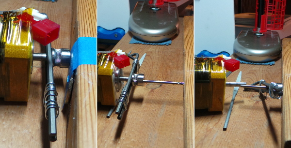
And the improvised gear puller worked! I wired a couple of hex keys together underneath the gear so I could pull on both sides at the same time with equal force. Then I started with a large washer taped to a bit of 2x2 to give something to push against. That got the gear pushed out to the end of the motor shaft (with human power only, employing the miracle of opposable thumbs to press on the 2x2 while pulling hex keys with my fingers - no C clamps required), but it was still clinging to the shaft tight as a tick, so I drilled a small hole in the 2x2 and left the drill bit in the hole and pushed again with the drill bit aligned on the end of the shaft, and the dadgum pulley finally came off (whew!). I'll have to smooth the shaft some and see if I can get the gear to slide without needing a hydraulic press to get it positioned. Maybe someday, I'll be ready to try printing again...
...Whew! Finally seem to have everything assembled, only to run into yet another hitch: The nozzle on the stock solidoodle hot end is a lot higher than it was in the old jigsaw assembly. Even when I put back the original very short z-stop, I still can't raise the Z screw enough to quite get the bed to reach the nozzle. I'll have to see if I can raise all the leveling screws enough to make up the difference :-).
I thought it might be impossible to get a bed level that worked with the stock solidoodle hot end, but I just needed to be really careful finding the sweet spot. My first print after installing new carriages, new extruder, and direct Y drive is a calibration cube:
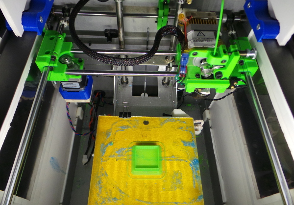
So I didn't break it forever, it's alive! (And I didn't detect any obvious signs of problems that might be from the hot end wobbling in the new mounting.) I started taking everything apart after work on a Friday, and now I finally have it printing again on Tuesday evening. I didn't work on it continuously during that period, but I certainly worked on it quite a lot (and I'm on vacation, so real work didn't interfere). All the little unexpected hitches definitely slowed me down.
Soon I'll want to make sure everything is calibrated perfectly then try some cylinder prints to see if all this work was worth it.
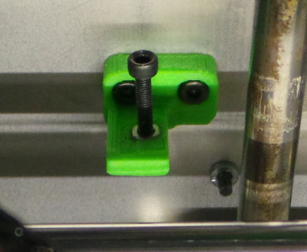
I'll also want to print a new z stop that is shorter since I have the original z stop back in there at the moment, and the screw always vibrates loose in it:
Note: Bed level is really important now that the carriage can't rock any longer. With the new carriages I was getting an occasional clunk noise from the extruder when I had the first layer squished too much. Making a mark on the hob gear and extruder shaft and watching when it clunked, I could see the shaft slipping backward a bit. I suppose the filament didn't have enough room, and back pressure built up too much for the extruder to handle. In some ways this is a good thing, since I was able to crank down the Z stop screw a bit to make the first layer thicker and do another test print until I got a print with no clunk, but still a uniform 1st layer. I think that's the perfect bed level. And now if I get clunks on just one side of the bed when printing large objects, I'll know it isn't entirely level.
Another note: If I ever have reason to replace the fishing line on the X carriage, I should first make a part I can tape on the bottom to hold the nut in place, then use a shorter screw to hold the washer since the 35mm screw I used sticks out enough to hit the drive pulley if I move too far left (so I'll need to avoid doing that while I have the long screw on the carriage :-). Perhaps I should also switch to one of the really short 6mm screws on the right side to give more room for the left side screw to be threaded into the carriage.
And apparently seemingly imperceptable rocking of the hot end in the extruder causes mysterious problems: See Cable Chain for the problems I had with the first "real" thing I tried to print after this upgrade. A small strip of thin aluminum foil wrapped around the top of the hot end where it slides into the extruder seems to have fixed it (but I'm also thinking about making an accessory clip with a nut trap so I can force the clip against the hot end. Another source of rocking was the bolts holding the extruder to the carriage. I tightened them down some which cut down on rocking of the entire extruder assembly. The print quality after these fixes was vastly improved.
Go back to my main Solidoodle page.