Calibration Time
I printed this piece with 0.2mm layers from a step model I made in openscad that is 15mm thick and has three steps each 20mm long and high:
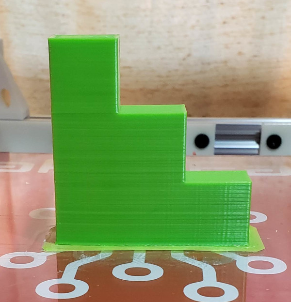
Vertical step measurements:
| Steps | Height | Inc |
|---|---|---|
| 3 | 62.154 | 20.854 |
| 2 | 41.300 | 20.574 |
| 1 | 20.726 |
Step measurement in X:
| Steps | Width | Inc |
|---|---|---|
| 3 | 59.893 | 19.888 |
| 2 | 40.005 | 19.812 |
| 1 | 20.193 |
The thickness measurement (Y direction) was 14.445
Seems like X and Y aren't moving far enough and Z is moving too much. I have plans for a more accurate X,Y calibration, but to fix Z seems like I ought to multiply the current steps per mm by 40.0/(62.154-20.726) or 0.96553 (ignoring the first step since layer 1 thickness is often off for different reasons than Z steps per mm).
I modified the steps per mm in the config, and printed one of the little 5mm step pieces to see how it comes out:
Vertical step measurements:
| Steps | Height | Inc |
|---|---|---|
| 5 | 26.416 | 5.588 |
| 4 | 20.828 | 4.826 |
| 3 | 16.002 | 5.690 |
| 2 | 10.312 | 5.207 |
| 1 | 5.105 |
Am I screwing up the calculations? It still seems like I need to reduce the steps per mm again by almost as big a factor as I did the first time. Of course, the tiny 5mm steps has problems with cooling which could distort things.
If I calculate the step per mm from thread pitch and stepper motor and stepper driver, I get 1600 as the value I should use, which is way larger than the value I can come up with previously by measuring thickness of printouts. I don't understand what is going on for sure, but I'm setting it back to 1600 for now [bad idea].
Moving on to checking the X,Y calibration. Here's a random pattern I cut from a 6x6 inch sheet:
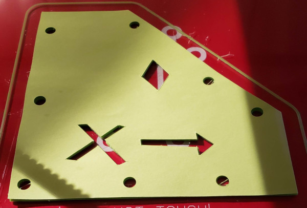
I scanned it, converted it to a .svg file in gimp, imported the .svg into openscad and extruded it to 1mm thick, generated the .stl file (used online tool to fix the file which for some reason wasn't manifold), then printed it:
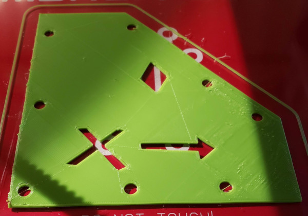
That first picture was the pattern sitting on top of the printout. It sure seems to line up all the holes and everything pretty well, so I think I can say X and Y are calibrated pretty well.
Of course there are other problems like the nozzle apparently digging into the surface a bit over on the right side, but that could just be bed level needing adjustment.
Now if I could only figure out the Z axis issues that confused me above (Did I thimk backwards? If it prints too high does that mean I should increase the steps per mm rather than decrease them? [nope - increasing to 1600 made it move wayyy to much])
DOH! I found one problem: Updating the config file and power cycling the printer doesn't reboot the smoothie unless I also unplug the USB cable. The 1600 value is utter nonsense, 400 is much closer.
Meanwhile, back on Z calibration. I taped a nice metric steel ruler to a block of wood to hold it upright, then took pictures where the printbed rail touched it at the top and bottom of a lot of movement. I went from 133mm to 344mm which is 211mm. The actual amount I told it to move was 210mm, so that's pretty darn close. Did the same movement again just to make sure and got the same numbers.
So instead of 400 steps per mm, I want 400.0*(210.0/211.0) or 398.10426540284357 steps per mm. Let's try updating that (and correctly reboot the printer this time).
Hot dog! It moves to 343mm now. Don't think I can calibrate any better than that.
Used the little single wall cube I print for tests to measure the wall thickness. From my old solidoodle calibration, I read that a .4mm nozzle is supposed to lay down 0.48mm wide walls. The default extrusion multiplier of 1 was producing slightly thinner walls than that, so I changed it to bump up the extrustion multiplier a bit, and now get 0.48mm walls. Also measured the brim thickness and adjusted the Z level a tad to get a brim as close to 0.35mm as possible (the thickness it prints the first layer).
A tale of two prints
To test my new Z calibration with actual prints, I devised a new step model with step height exactly equal to a multiple of the 0.3mm layer height, and got this result on two different versions of the print:
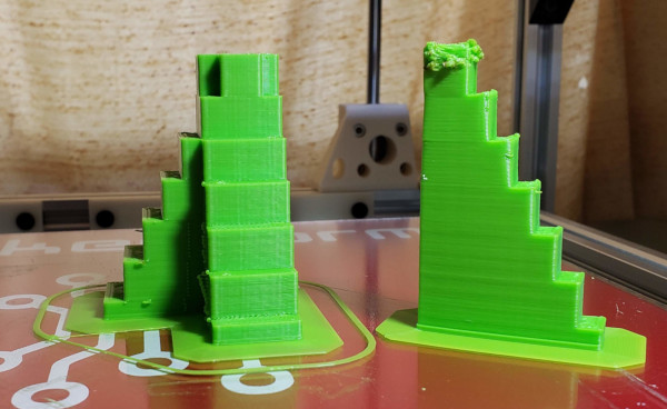
The melted one was the first one I printed, the much better one is the same openscad model made wider and rotated on itself to give it lots more movement before it comes back around to previously printed filament. Clearly I really need to get my cooling fan working :-). Perhaps also reduce the temperature I am using to extrude filament.
Checking all the measurments again:
| Steps | Height | Inc |
|---|---|---|
| 1 | 5.03 | |
| 2 | 14.81 | 9.78 |
| 3 | 24.92 | 10.11 |
| 4 | 34.90 | 9.99 |
| 5 | 44.68 | 9.78 |
| 6 | 54.56 | 9.88 |
| 7 | 64.62 | 10.06 |
The model has steps 9.9mm high. If I average all the measurements I took, I get 9.93 which is pretty close, and who knows how much slightly rough 3D printed surfaces affected my measurements (or not getting the micrometer exactly vertical for that matter). I guess this is as good as I'm likely to get it.
The ultimate test of calibration is printed parts fitting correctly. Here is the old cap on the extruder which has printed threads that hold down a little cone "collet"-like thing that is supposed to hold the tube in place:
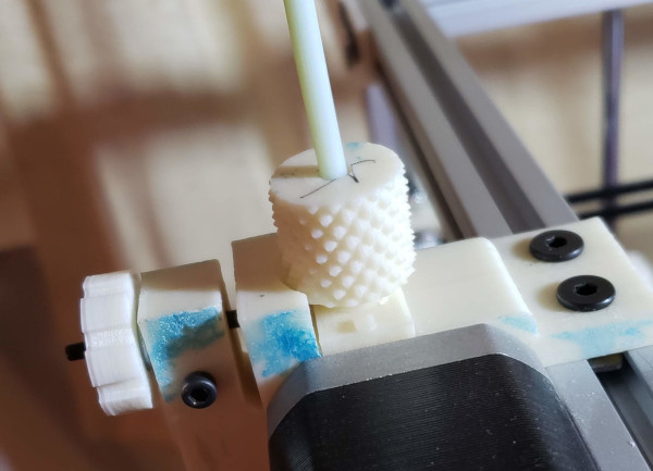
The collet doesn't work very well. It doesn't take too much to blow out the tube from the cap. I'm working on new caps that can hold commercial bowden couplers I ordered from filastruder.com. I decided a good test would be to see if caps and thread printed on the old solidoodle (white) and on Jiggit (green) were compatible, and they sure seem to be:
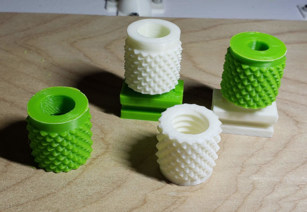
So when the parts come in and I can make exact measurements and finalize the cap design, I should be able to use new a new cap printed on Jiggit [turns out I used the one from the solidoodle after all].
Parts are in, and while I thought the metal one would look better, there would be lots of fiddly adjusting of the design for the hole to fit it and waiting for epoxy to dry, so I tried the plastic one with the teeth to grab the part, and it works fantastically well. The piece I already printed worked with no modification other than scraping off the layer one squishing. I set it in the hole then used a clamp to squeeze it down and set it in the plastic:
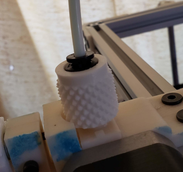
I just need to come up with a clip to hold it up so the tube itself won't shift when I retract filament. (It is bigger than the metal part, and a standard clip won't work).
Found one: I printed a few of the clips for the E3D plastic threaded version, and they fit the embedded plastic coupler I have perfectly. Right thickness, right diameter. Looks like I don't need to design my own.
I've got the Orion installed now, so printing the first layer too close should be a thing of the past. What I really need the better bowden connector for is being able to configure retraction so I no longer drool filament when moving without extruding. Time to investigate how to do that.
I found the retraction setting in slicr3 (found in extruder) and changed the original 2mm to 4mm and it seems to work much better with no strings left on the bed between the skirt and the brim (as an example), so maybe that's good now.
The next project to improve print quality is to get the PWM Cooling Fan mounted.
(After a coupole of iterations of shroud design, I seem to have effective cooling now).