Sonic Screwdriver
I'm trying to print the 11th Doctor Sonic Screwdriver Redrawn. My first attempt made me realize that printing tall things at high resolution is a challenge :-). The print head tends to knock the tall parts over when the bed vibrates or the thin plastic on overhangs curls up.
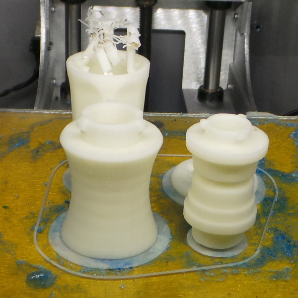
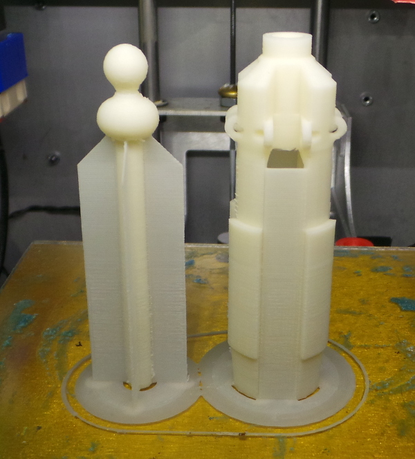
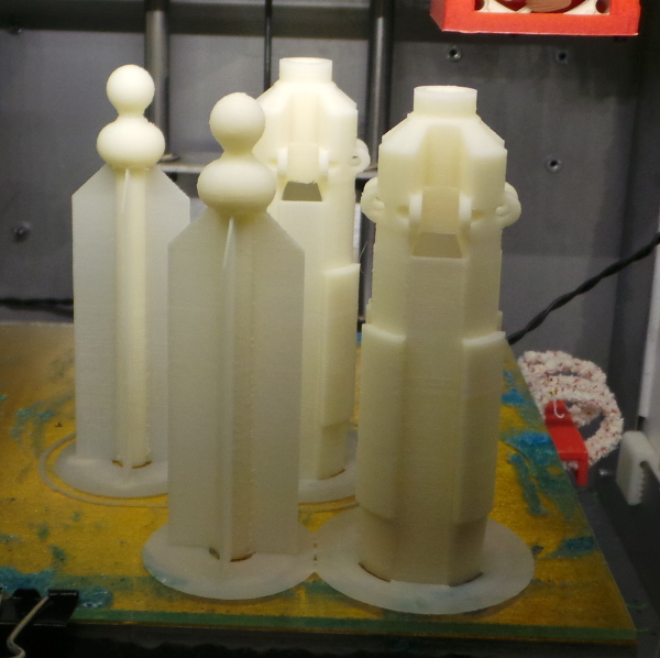
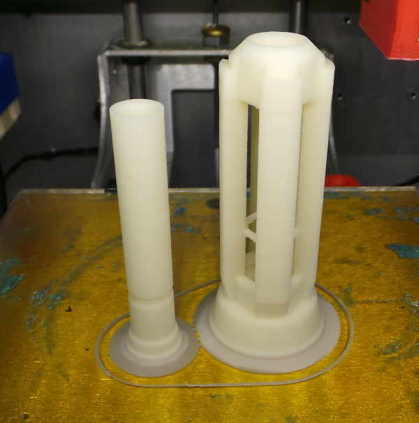
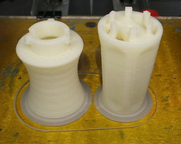
That challenge led me to add the X-Axis Stabilizer and the PWM Fan Mount, after that, I was actually able to print the two tallest parts at 0.1mm resolution (it took over 5 hours, mind you):
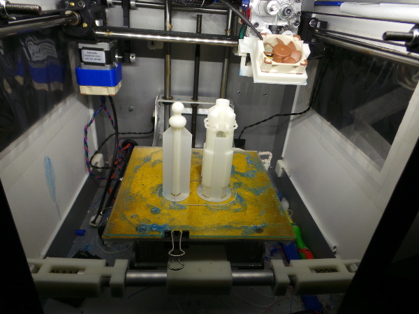
I'm planning to paint these natural ABS parts, by the way, so I'm not worried about the color.
Naturally, the first thing I did was snap one of the long prongs on the silver_cage_support.stl part when testing how springy it was after removing the support material (not very :-). It didn't snap all the way through, so I used a little acetone and tilted it back into place. I'll be more careful in the future.
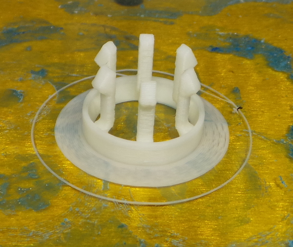
I printed the 4 prongs (they are easy - not very high), then tried to print the next highest set of parts: The gold_cage_hollow.stl and green_core_hollow.stl. Unfortunately, that dies horribly when it tries to print the bridge up around 6.4 cm high on the cage. Once again the head ran into the plastic part and knocked it over. So even with the stabalizer and the fan, I still have problems with rather large bridges (though it worked OK with the similar bridge closer to the bottom).
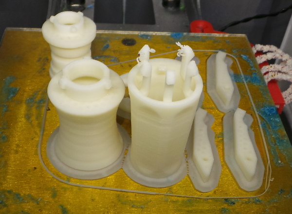
I next printed the 4 remaining shorter parts:
Three of them were a success, but the tallest of them, white_handle_hollow_twist.stl had problems with all the little prongs, knocking them off and generating a bunch of loose filament instead.
That leaves me with 3 parts I haven't yet printed. I'm giving them one more try with all the speeds cranked down about 75% (and the bridge speed cranked down even more). If this doesn't work, I guess I'll need to try doing all my calibrations again and perhaps finish some additional modifications before trying to print them again (I'm also really close to the end of the spool of filament, so I hope it doesn't run out before this last print finishes :-).
Slowing everything down seems to have worked for gold_cage_hollow.stl and green_core_hollow.stl, but white_handle_hollow_twist.stl still has problems with knocking the prongs off, so I'm down to one part not printed, and I need to try something drastic for it.
I'm going to use openscad to cut the prongs out of the top of the handle and print a ring containing them separately at 0.3mm resolution so there won't be as many layers to provide weak spots (and everything will be closer to the bed so the lever arms won't be as long). If I can get that to work, I can print the rest of the handle at 0.1mm then glue the prongs to the hole left in the top.
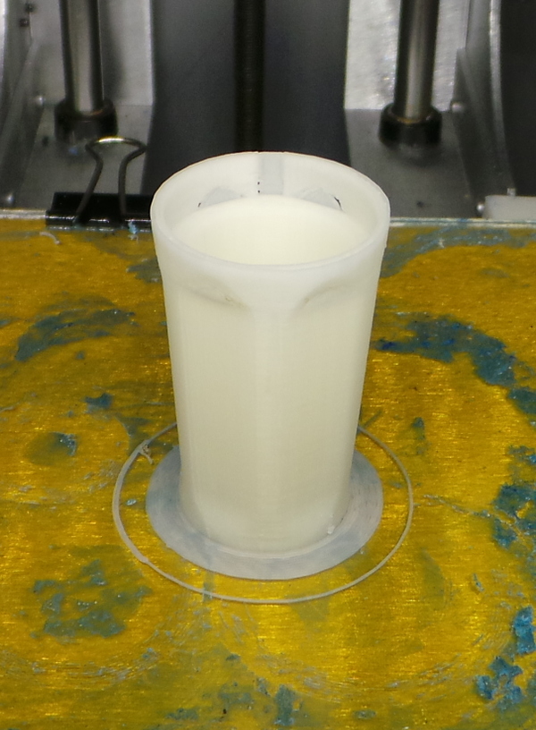
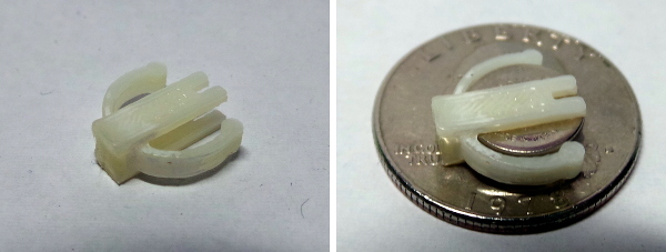
And it worked. The "crown" printed fine by itself at 0.3mm resolution:
Now I can print the leftover part of the handle at 0.1mm and see about joining the two parts:
Some patches are a little thinner than they should be, but it should work out OK once I get the parts glued together, sanded, painted, etc...
I now have all the parts printed. Next up I need to paint them with acetone for better strength, sand off any blobs and wot-not, then get them all painted the right colors. Finally, I should be able to assemble them into a completed sonic.

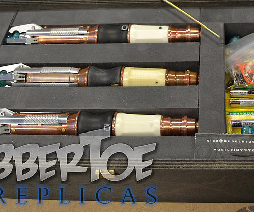
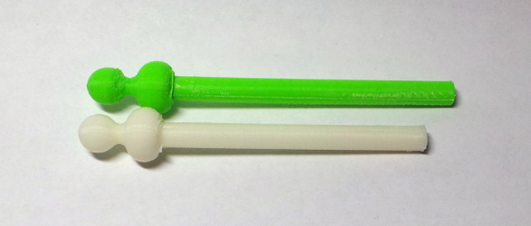
Time has passed, and I wanted to print a new green tip that is hollow so that I could run a small green LED up to the end and create a thing from Parametric button cell battery holder to hold a battery (reminder - negative connects to short wire on LED, positive to long wire), then toss in a pushbutton similar to the official models from Rubbertoe:
Weirdly, however, when printed the new part from a modified STL file that is exactly the same height as the original, it printed almost a centimeter taller.
In between the two prints, I swapped in a M3 Z screw, but the height of everything I printed seemed perfectly fine until I got to this one part which I printed at 0.1mm layer height, so this was very mysterious. Before I tried to understand it, I wound up doing a slew of other modifications to the printer. I'm now back to look at it again, and to start with I'm printing both the tall parts again at 0.2mm resolution to see how high they come out with a resolution that seems to have been accurate for other things.
Whatever I figure out, I'll probably want to reprint everything because the mods have made the printer fantastically more accurate than it was before.
OK, the new 0.2mm parts finished printing, and if I measure the parts with my calipers (another item of unknown accuracy :-), I get these numbers:
| Part | Height |
|---|---|
| Original .1mm (natural) | 89.63 |
| Bad .1mm (green) | 98.47 |
| New .2mm (natural) | 89.55 |
Since the .stl file model is actually 90.11, I'm not sure what to make of any of these numbers, but the new part I just printed and the original 0.1mm part I printed before the Z axis change are very close to the same size. In about 5 hours, I'll find out what size part I get when printing at 0.1mm. I kept every setting except the layer height absolutely identical. I'd certainly expect it to be identical (but smoother), especially since the layer height should work out to a nice even integer multiple of steps in both the 0.1mm and 0.2mm case using the M3 Z axis screw.
...Five hours later, and the .1mm prints are finished:
If I compare them with the .2mm prints, I see this:
They certainly seem to be the same height, so I have no idea what the heck happened to make the green print come out so tall. I guess it will remain an unsolved mystery. I'll have to guess that I accidentally leaned on the keyboard and increased the Z scale factor when I loaded the model (without noticing).
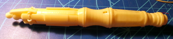
I now have the remaining two very tall parts printed:
The remaining parts are shorter and shouldn't take as long (but there were a lot of them, so it took longer).
In a tribute to how impossible it is to print the little prongs on top of the handle piece (at 0.1mm resolution), they still got screwed up even with all the mods I've done to improve accuracy.
Having thought about it some, what I really want to do is change the black and white handle pieces to include a place for a M3 bolt and nut so I can screw those halves together and have easy access to change the battery for the LED.
Finally got everything to print and here are the parts I modified:
The hollow green tip has already appeared above, here is the openscad code I used to modify the part:
// Make the green tip hollow so I can run a small LED up through it.

rad = 1.8;
toth = 90.11-2;

difference() {
   translate([-(12.7+25.4/2), -(12.7+25.4/2), 0])
      import("11th_Doctor_Sonic_Screwdriver_Redrawn/green_tip_support.stl");
   union() {
      translate([0,0,toth-rad])
         sphere(r=rad, $fn=64);
      cylinder(h=0.01+toth-rad,r=rad,$fn=64);
   }
}
The battery holder for a CR1025 3V button cell:
// Invent a really small battery holder I can wedge into the black handle

battery_diam = 10;
battery_width = 2.5;

cylwall=0.48*2;

nub=2;
nub_x=4.7;
nub_y=2.7;

poly_x=4*nub_x;
poly_y=4*nub_y;

leg_thick=1;

// Two batt_leg() parts get glued to either side of the batt_ring() to form
// the complete battery holder part. This part gets glued into the black
// handle (after adding the wires because there is no way to fiddle the
// wires easily once the part is glued in).
//
module batt_leg() {
   union() {
      difference() {
         cube([4,2+battery_diam,leg_thick]);
         translate([(4-1)/2,-0.01,-1])
            cube([1,2.5,leg_thick+2]);
         translate([(4-1)/2 + 1/2,2.5+battery_diam/2-0.1,leg_thick+1/2])
            rotate([95,0,0])
               cylinder(h=battery_diam/2, r=1/2, $fn=32);
      }
      translate([1,2+battery_diam-1,0])
         cube([1,1,battery_width+leg_thick]);
   }
}

// This is a part used to help form the space we'll subtract off the black handle.
//
module solid_batt_leg() {
   union() {
      cube([4,2+battery_diam,leg_thick]);
      translate([1,2+battery_diam-1,0])
         cube([1,1,battery_width+leg_thick]);
      translate([4/2, 0, -1.5/2])
         rotate([-90,0,0])
            cylinder(h=2+battery_diam,r=1.5/2,$fn=64);
      translate([2-1.5/2,0,-1.5/2])
         cube([1.5,2+battery_diam,0.01+1.5/2]);
   }
}

// Here we have a small partial ring with little nubs on the end. It is
// springy enough to hold the battery when slipped into it.
//
module batt_ring() {
   union() {
      difference() {
         // Make a thin cylinder
         union() {
            cylinder(h=battery_width, r=cylwall + battery_diam/2, $fn=64);
            // With a mounting area on top where side peices will be glued.
            translate([-2,0,0])
               cube([4,2+battery_diam/2,battery_width]);
         }
         translate([0,0,-1])
            cylinder(h=battery_width+2, r=battery_diam/2, $fn=64);
         // Cut a wedge out of it
         translate([0,0,-1])
            linear_extrude(height=battery_width+2)
               polygon(points=[[0,0],[poly_x,-poly_y],[-poly_x,-poly_y]]);
         // Cut slot in mounting area
         translate([-1, (2+battery_diam/2)-0.99, -1])
            cube([2,1,battery_width+2]);
      }
      // Put a couple of nubs on the end of the cut wedge
      translate([nub_x, -nub_y, 0])
         cylinder(h=battery_width, r=nub/2, $fn=64);
      translate([-nub_x, -nub_y, 0])
         cylinder(h=battery_width, r=nub/2, $fn=64);
   }
}

// Make printable part with the battery ring and two legs which can
// be printed, then assembled.
//
module print_battery() {
   union() {
      batt_ring();

      translate([-11,-battery_diam/2,0]) batt_leg();

      translate([11-4,-battery_diam/2,0]) batt_leg();
   }
}

// Make shell to represent the space the battery part needs, this gets
// subtracted off the black handle
//
module batt_shell() {
   extra_rad = 1+ cylwall + battery_diam/2;
   rotate([90,0,0])
   translate([0,battery_diam/2,-battery_width/2])
   intersection() {
      union() {
         batt_ring();
         translate([-4/2,-battery_diam/2,0.01-leg_thick])
            solid_batt_leg();
         translate([0,0,battery_width])
            rotate([0,180,0])
               translate([-4/2,-battery_diam/2,0.01-leg_thick])
                  solid_batt_leg();
         cylinder(h=battery_width, r=extra_rad, $fn=64);
         translate([-extra_rad, -extra_rad, 0])
            cube([extra_rad*2,extra_rad,battery_width]);
      }
      translate([-50,-battery_diam/2,-50])
         cube([100,2+battery_diam,100]);
   }
}
Which looks like this when assembled:
These are the mods to the black and white handle parts to allow them to be screwed together and add the battery holder and a tiny push button to the black handle part:
include <newbatt.scad>

// hack the black handle to do three things:
//
//   1. Cut hole in side for push button backed by bracket for button
//      to rest against (and be glued to eventually).
//
//   2. Build bar across the bottom with a nut trap on top and hole
//      for M3 bolt.
//
//   3. Add place on bar to press fit button cell battery holder.
//

button_wide=3.52;
button_high=6.11;
button_thick=3;

// Import black handle and center it
//
module black_handle() {
   render() translate([-9.49-(31.83/2), -238.09-(31.83/2), 0])
      import("black_handle_hollow_arduinomini.stl");
}

// Build a bracket for the base of the button to rest against (this is going
// to be rotated around to same angle as button, so the bracket needs to be
// shaped with a steeper angle to be printable).
//
module button_bracket() {
   bracket_high=button_high-2;
   translate([1,0,bracket_high+1])
   rotate([0,-30,0])
   difference() {
      rotate([0,30,0])
         translate([0,0,-bracket_high])
            rotate([0,30,0])
               difference() {
                  rotate([0,-30,0])
                     translate([-2.5,0,0])
                        translate([0,-(button_wide+6)/2,0])
                           cube([2.5,button_wide+6,bracket_high]);
                  translate([-5,-30,-50])
                     cube([50,50,50]);
               }
      translate([-25,-25,0])
         cube([50,50,50]);
   }
}

// Module to generate the handle with the button hole and bracket added to it.
//
module handle_plus_button() {
   difference() {
      union() {
         black_handle();
         rotate([0,0,60])
            translate([12.05, 0, 3])
               rotate([0,-16.5,0])
                  button_bracket();
      }
      rotate([0,0,60])
         translate([12.05, 0, 3])
            rotate([0,-16.5,0])
               translate([0,-button_wide/2, 0])
                  cube([button_thick,button_wide,button_high]);
   }
}

// Size of M3 nut for nut trap (plus a bit of slop)
//
m3_width=5.47+0.2;      // flat to flat width of M3 nut
m3_thick=2.22+0.2;      // thickness of M3 nut
m3_head=5.5/2;          // radius of M3 head

// Handy hexnut shape
module hexnut(nutwidth, nutthick) {
   intersection() {
      translate([-nutwidth,-(nutwidth/2),0])
         cube([nutwidth*2,nutwidth,nutthick]);

      rotate([0,0,60])
         translate([-nutwidth,-(nutwidth/2),0])
            cube([nutwidth*2,nutwidth,nutthick]);

      rotate([0,0,120])
         translate([-nutwidth,-(nutwidth/2),0])
            cube([nutwidth*2,nutwidth,nutthick]);
   }
}

// Bar to cross bottom holding a nuttrap and a 3mm hole
module nutbar() {
   difference() {
      union() {
         translate([-29/2,-5/2,0])
            cube([29,5,3]);
         cylinder(r=4.5,h=5,$fn=64);
      }
      translate([0,0,5.1-m3_thick])
         hexnut(m3_width, m3_thick);
      translate([0,0,-1])
         cylinder(r=3/2,h=10,$fn=64);
   }
}

// The accumulated new handle shape including the bar across bottom
module handle_plus_bar() {
   union() {
      handle_plus_button();
      nutbar();
   }
}

// The final part adds another bar where we'll subtract off the battery holder
// shape to leave a place to glue the battery holder.
difference() {
   union() {
      render() handle_plus_bar();
      translate([-6/2,-14,0])
         cube([6,12,2]);
   }
   translate([0,-7,-0.01])
      batt_shell();
}
// Modify the white handle to print just some stubs of the prongs at the top
// to position the gold ring correctly for glue.
//
// More importantly, build an arch with a 3mm hole in the center to print
// at the top which will be used to glue in an M3 bolt that will be used
// to screw the while handle/gold ring to the black handle.

flat_height=46.02;
ring_height=4.62;

module white_handle() {
   translate([-10.92-28.97/2, -10.92-28.97/2, 0])
      import("white_handle_hollow_twist.stl");
}

module bottom_arch() {
   intersection() {
      difference() {
         cylinder(r1=23/2, r2=28/2, h=15);
         cylinder(r1=22/2, r2=6/2, h=15);
      }
      translate([-9/2, -28/2, 0])
         cube([9,28,15]);
   }
}

module top_bar() {
   difference() {
      union() {
         intersection() {
            difference() {
               translate([-9/2, -28/2, -3])
                  cube([9,28,3]);
               translate([0,0,-4])
                  cylinder(h=10,r=3/2,$fn=64);
            }
            translate([0,0,-4])
               cylinder(h=10,r=28/2,$fn=64);
         }
         translate([0,0,0.01-15-3])
            bottom_arch();
      }
      translate([-25,20,-8]) rotate([0,90,0]) cylinder(r=10,h=50,$fn=64);
      translate([-25,-20,-8]) rotate([0,90,0]) cylinder(r=10,h=50,$fn=64);
   }
}

union() {
   difference() {
      // Start with regular while handle part
      white_handle();
      // chop off the silly prongs that never print so they are just below the
      // height of the ring.
      translate([-25,-25,flat_height+ring_height-0.1])
         cube([50,50,50]);
   }
   // Add in a bar constructed so it can print at the top of the piece
   translate([0,0,flat_height])
      rotate([0,0,30])
         top_bar();
}
Here's how they came out when printed:
Now I need to get the parts dipped in acetone for strength, sanded and painted, hook up the wires and put it all together and I'll finally have my sonic screwdriver...
I got the parts dipped and burrs and bumps cleaned and tried a test assembly (with just one of the 4 front prongs) to see how it all fits:
Looks pretty good (even if the incandescent light does turn it yellow/orange), and the M3 bolt to hold the central handles together works well. You can also see the hole where the push button to operate the green LED will go. Now to take it back apart and start painting...
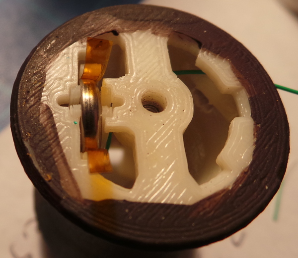
Here you se the battery holder inserted into the black handle piece. A couple of small wires are hooked over the legs in the battery holder and glued in place so the bare wires inside the holder will contact either side of the battery.
And here is the finished product. Most pieces glued together, but the M3 bolt holding the white and black handle together (with the gold ring glued to the stubs of the prongs on the white handle.)
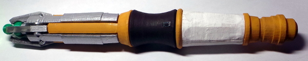
The negative side wire was run out through the bottom part of the hole for the push button, cut near the handle and soldered to one connector on the push button, the remaining wire was then soldered to the other connector and run back through the top part of the button hole. The button was then pushed into place in the hole (after a bunch of filing to make the hole an exact push fit). The wire were run up through the top of the handle and the green core and gold cage where I cut them to length, and soldered them to the LED (remembering to shove a piece of heat shrink tubing over one wire before soldering). The LED was tested and worked, so I then shoved it as far as it would go up the green tip, fished the other end of the wires out of the black handle so I could take up the slack, and carefully shoved the green tip and silver cage assembly over the top, pulling the wires back through the handle as I went. Stuff the wire slack back up into the black handle, screw on the white handle, and I'm done!
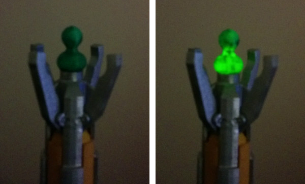
If you look real close you can even see the tip light up when I press the button (especially in these grainy low light images).
Go back to my main Solidoodle page.