Fence Foolery
The fence is pretty hopeless (as everyone with one of these saws always seems to conclude), but I'll see what I can do with it till the day comes when I decide to spend hundreds on a new fence.
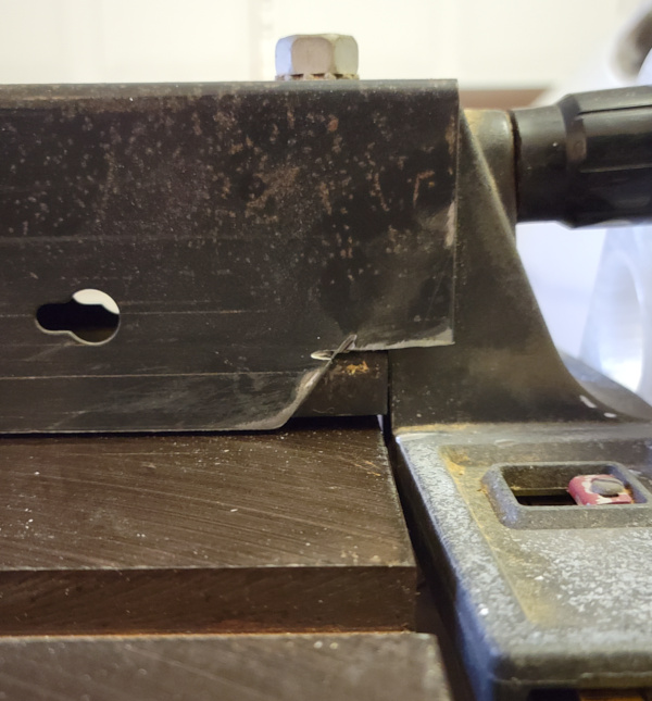
One long standing problem I finally fixed: The rip fence always had the corner near the handle bent out a smidge, so if something slid past that point it would shift by that same smidge when it passed the bent corner. After many attempts at bending it, I said to heck with that and used a cutting wheel on my Dremel to simply cut the bent corner off. Finally, there is no perceptable shift when I slide a board past that corner.
The fence also didn't slide very smoothly, but some paste wax on the rails made it work much better (a hint from the internet).
After getting the blade aligned, I tried to use the same jig on the fence, but it really never got better. Moving it always results in random variations. It isn't consistent at all. The best I could do is try to make sure it never winds up pinching the cut at the back end of the blade and if it going to be off, it is always off by being farther away from the blade in the back.
I suppose I could bolt a plywood or plastic face to it to make it smoother, but that wouldn't do much for the random variation in positioning it always has.
This video might provide some handy tips for using the saw while figuring out a better fence:
Table Saw Jigs to Align a Crappy Table Saw Fence
Actually, the final jig demonstrated in that video gave me an idea: What if I just made a fence that was a plywood angle and stuck a magswitch at each end? I could use the two sticks jig to get it parallel and the right distance, then turn on the magswitch at each end to hold it there.
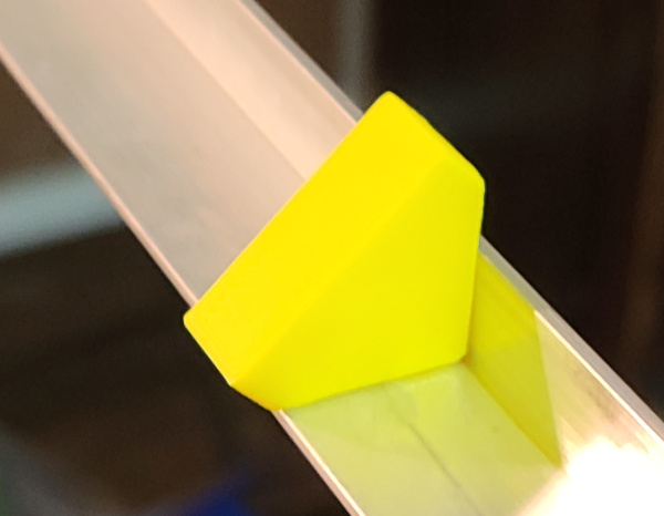
I've started prototyping bits that will eventually become the jig for fence positioning. First up, just make sure I can build the right size and shape for the aluminum angle to slide on:
Next prototype a mechanism for locking down the aluminum:
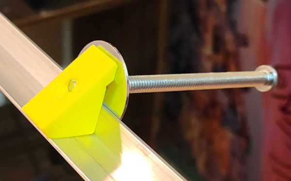
The idea will be to thread a short piece of 1/4-20 allthread through the block (not so far it sticks out the bottom) and glue it in place (simply tapping threads in the plastic should be fine with the addition of glue), then a knob with an embedded 1/4-20 nut can lock the angle in place by pressing down on it with a fender washer that has some cork stuck to the bottom. The plastic extension printed out the side makes sure the pressure is even instead of tilting the washer and making it force the angle to slide up or something.
Probably need smaller diameter fender washer to keep it up off the saw top (1 inch should be good, I think the ones I have are 1 1/4).
Note that I've picked an angle that is 1/2" by 3/4", so the 1/2" side is the side I clamp because there is room for the threaded rod, the 3/4" side will be where the ruler gets glued.
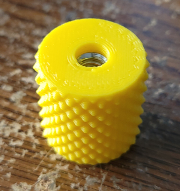
I've now printed a knob for the lock bolt. I used a knurl library for OpenSCAD to get the surface, and I edited the gcode to insert a pause at the layer where it is about to print the bridge over the 1/4-20 nut shaped hole I put in the model so I could insert the nut to embed it in the print:
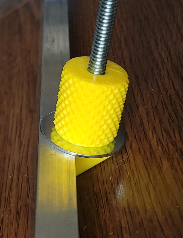
Using a bolt as a temporary stand in for a small piece of allthread, here's what it looks like clamping the angle:
Aside:
A brief description of embedding things in prints with Cura and Octoprint is probably worth adding here. (If you use different software, you are on your own :-).
Slice the model in Cura, then use preview mode to see which layer starts printing the bridge over the nut shaped hole. For this example that shows layer 30 in the preview slider.
Do not send that gcode to Octoprint, instead save it to disk.
Use editor to search for (in this example) "LAYER:29". For some reason the comments Cura puts in the gcode start numbering from 0, but the preview interface numbers from 1, so you need to be careful about that.
Now insert this gcode fragment after the comments for layer 29:
G28 Y0
G0 X0 F4500.000
M1
M105
You'll need to modify the first two lines for your printer. In my case this moves Y to home, and X to zero, which is the position that gets the print head as far out of the way as possible on my old solidoodle.
Save this file, then upload it into Octoprint and start printing.
When Octoprint gets to the M1 command, it will pop up a warning and pause the print.
Now is your chance to pop the nut into the nut shaped hole. This is much easier to get squarely inside the hole if you thread it on the end of a bolt to use as a handle, then unscrew the bolt once it is in the hole. If it isn't inserted so it is below the current top of the print, then something has gone wrong and you shouldn't try to keep printing, but cancel the print instead. Maybe you need more slop for the bolt to fit easily or you measured it wrong...
If it looks good, hit the Resume button in Octoprint, and it will start printing again, embedding the nut in the middle of the print. Be ready to hit the pause button if horrible noises start :-).
In my case there were a few strings across the hole, but they were easy to remove with some tweezers.
OK, back to the actual fence jig parts.
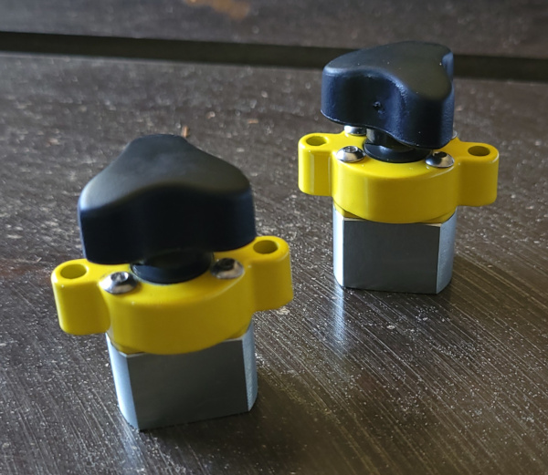
My magswitches arrived. They are designed to fit in a 1 inch hole in 3/4 inch plywood, so that is what I'll be making the fence from. I certainly can't move them by hand when they are turned on:
I've printed the simple jig (the complex jig will have a place to mount a magnifier bar over the measuring tape). Without the angle installed:
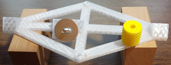
With the angle installed, the bolt sticks out below the 1/2 inch side so the angle rests entirely on the 3 supports printed on the jig:
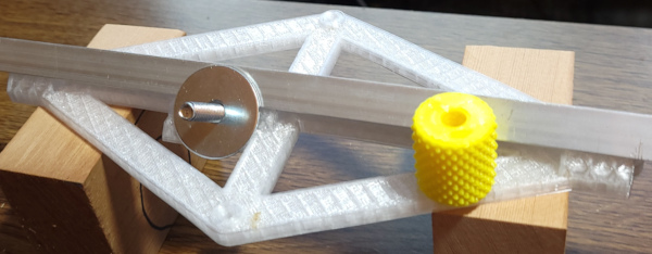
Screw the knob down, and the angle is secured in position:
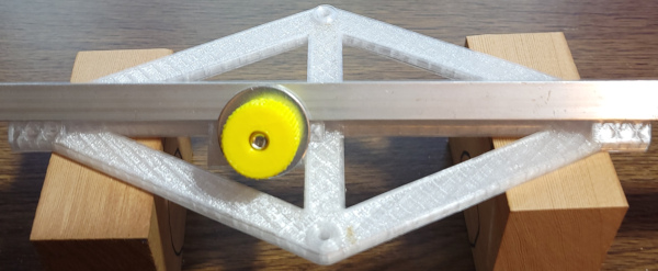
The front side is where the tape will go on the complex version of the jig:
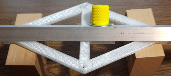
I haven't yet secured the threaded rod with glue, and I need to get one inch fender washers that won't stick out below the jig (won't need to prop it up on blocks after that). Also planning to stick some cork on the bottom of the washer to make it grab better.
Meanwhile, the UHMW miter bar strip arrived from Peachtree Woodworking, and the strip designed specifically for the slightly narrow miter slot on the Craftsman fits flawlessly. I also cut my aluminum angle into two 24 inch pieces (one for each probe) and put a pointy end on them. Here is everything laid out on the saw:
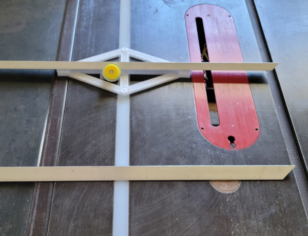
There is enough miter bar material to last quite a while for making new jigs or sleds, etc.
I'm now working on the holder for the magnifier bar to go on the complex jig (not yet completed).
I've cut one end off the magbar (I picked this one because it already had a thin red line down the middle, lots of others had fat yellow lines). I traced the outline of the cut off piece, scanned it in, and imported the image in OpenSCAD where I played around to determine the best fit for the circle shape. I then printed a few different test pieces with different amounts of slop to find the best push fit I could get:
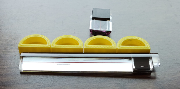
The best fit turned out to be 0.05mm smaller than the model I created (I guess the pencil lines made it look bigger).
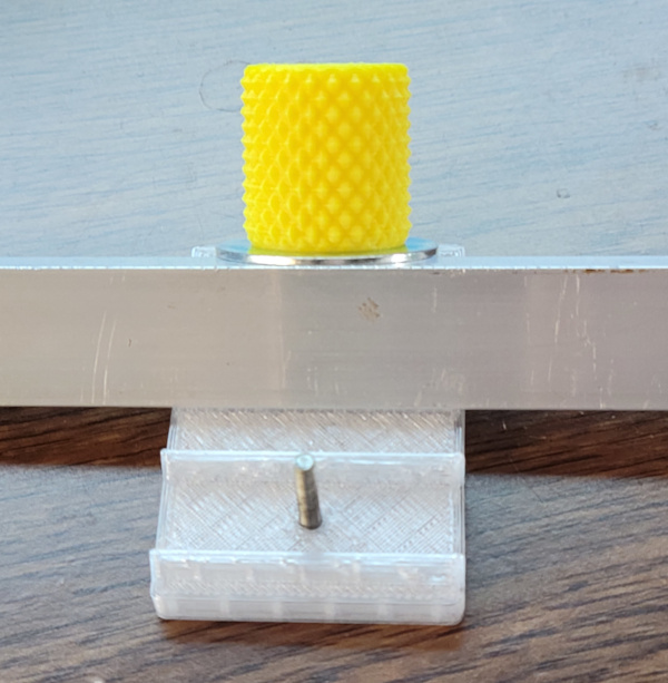
I've printed a prototype for the bit of the complex jig the magnifier bar will sit on as well as the magnifier bar holder. Here's the base piece:
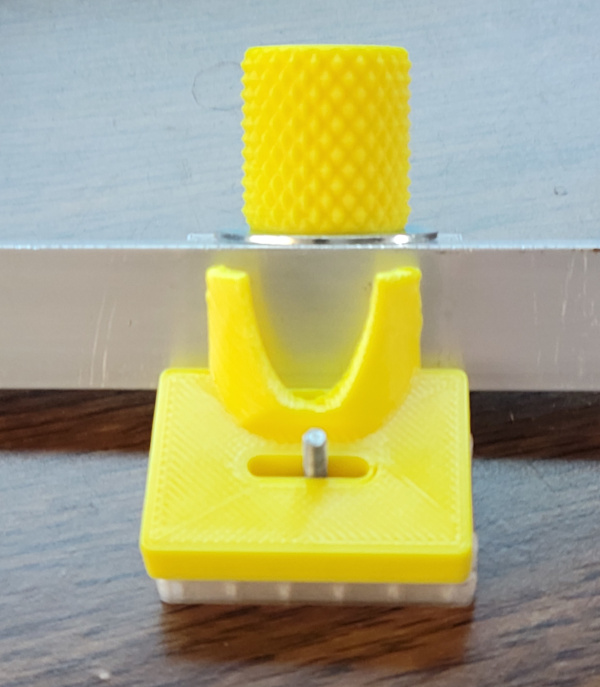
Now I add the magbar holder which can slide back and forth a total of 12mm (that's how long I made the slot):
Finally here's the magbar resting in the holder:
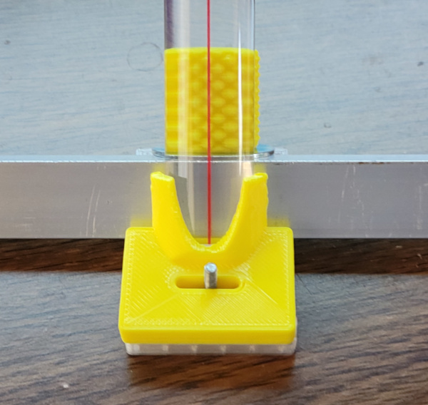
Everything seems to fit OK, so I guess I should print the full jig. I also need to design and print a knob to hold an M3 nut for locking the magnifier in place. In the final assembly the magnifier will be cut shorter and glued into the holder.
I've printed the fancy jig now, and the knob for locking the magnifier position. I've cut a chunk of the magnifier to length, and everything is ready to be glued now:
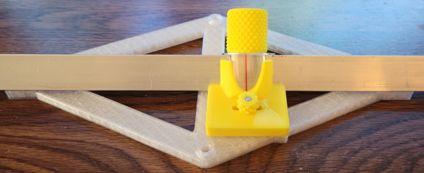
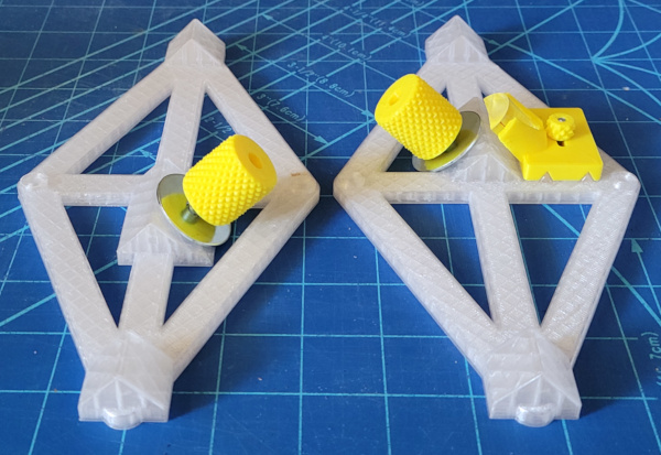
Now I've got the bits of threaded rod glued into the jigs and the chunk of magnifier glued into the holder and made a tiny knob with an embedded M3 nut to secure the holder position:
I've printed a drilling guide to get the pilot holes for the #8 wood screws in the exact right places to be able to screw the the miter bar on to the jig. The drill guide can also serve to show exactly where the cut the bar:
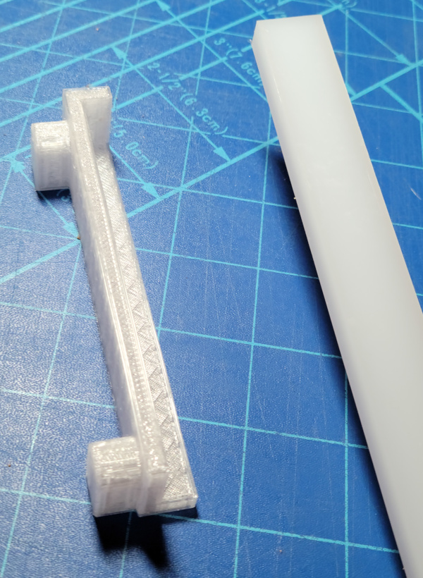
Flip the guide over and it fits on the bar like so:
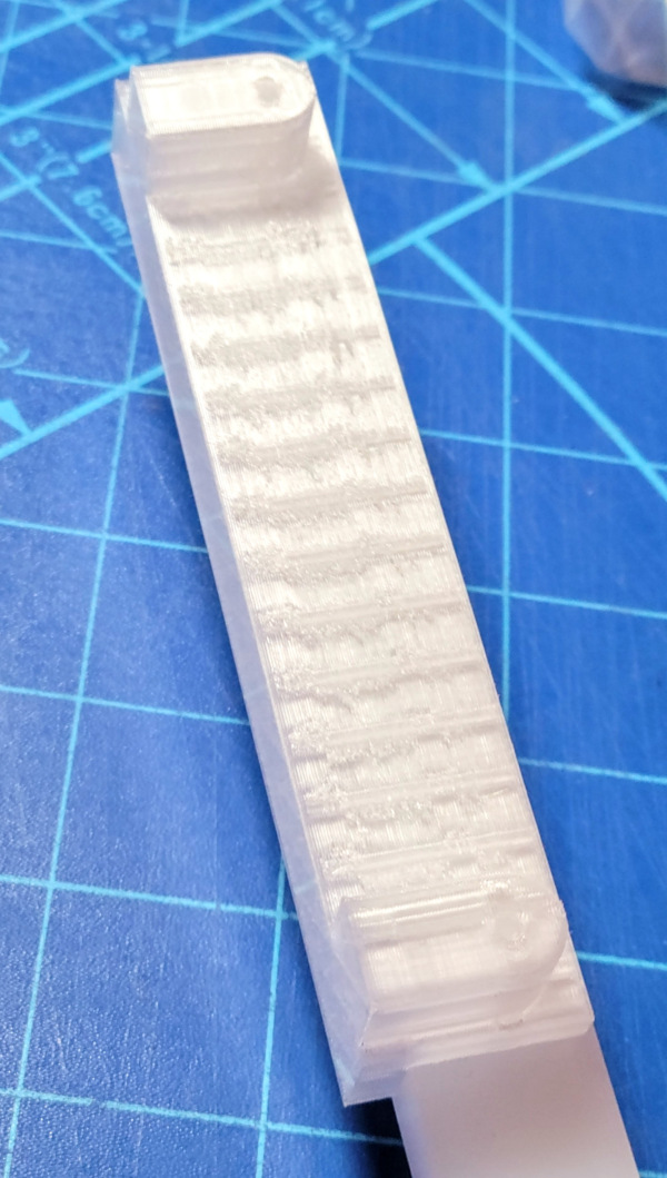
Comparing the drill guide to the jigs, the guide holes do look dead center in the screw holes, so this should work well.
The drill guide worked great. I've secured the miter bar chunks to the jigs and they slide nicely. Now I can find where the zero position of the tape I'll stick on should go:
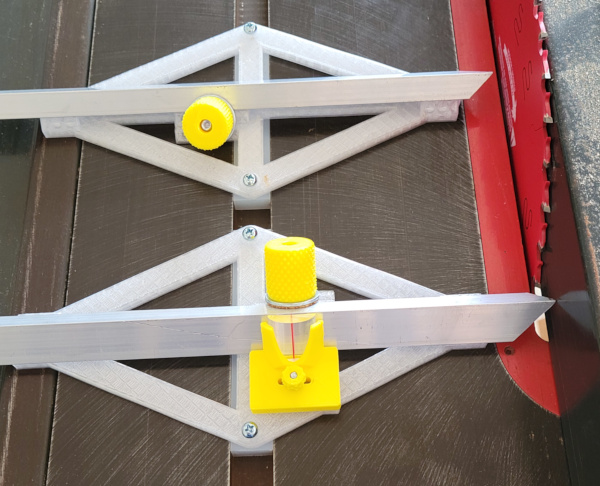
I've got the fence just touching the blade and the probe extended to touch the fence, so the zero position should be right where the red line on the magnifier currently points. Now just have to get the tape put down straight...
Not trusting myself to line the tape up by hand, I made a mini version of the technique demonstrated in this video. The angle sits inside the kerf of a slot and is clamped to the wood so it is flat against the edge of the slot:
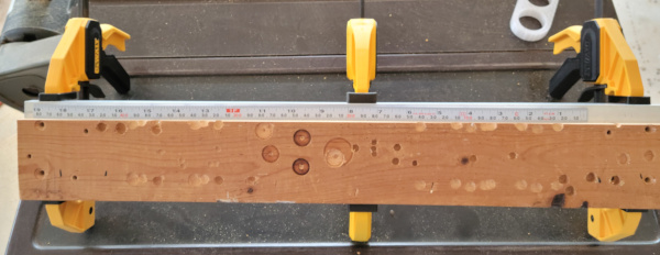
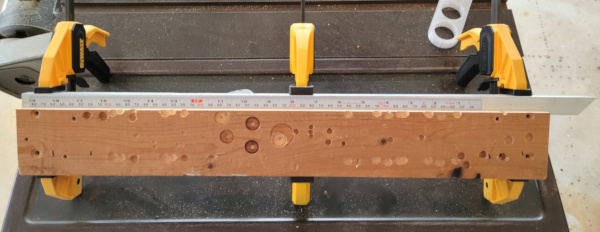
That allowed me to stick the tape down a little at a time keeping the edge against the wood and I successfully got it on perfectly straight:
The last step was poking the fence once again with it set to zero and adjusting the position of the magnifier a fraction of a millimeter to be exactly over the zero line:
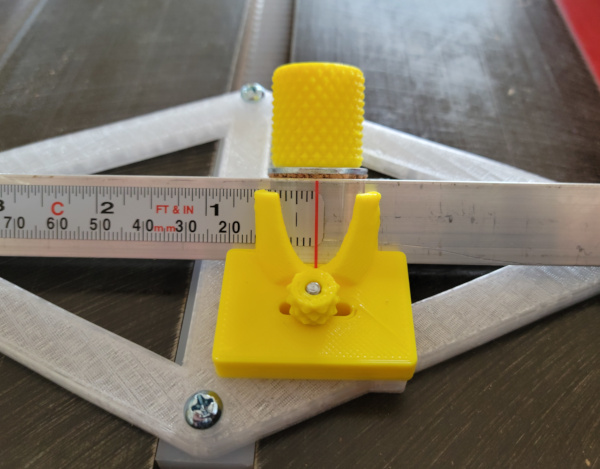
The tape I used was this Starrett one which I only used 19 inches of, but maybe the rest will be useful someday. I wanted inches and centimers and I need it to read right to left, and the 12 foot length was the one I could find
So the jigs are complete, now all I need is the fence with the magswitches to lock it down in the position I determine with the jigs.
All the OpenSCAD and stl files for these jigs are on thingiverse as thing 5330051.
...Time has passed, and I managed to get some 3/4 inch baltic birch plywood and made my fence hack:
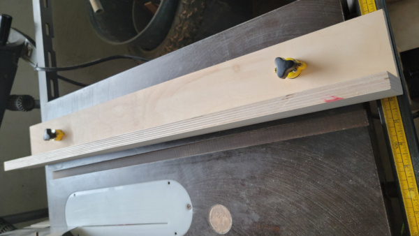
Seems to hold pretty well with the magswitches, but can rock a bit due to the switches not being the exact same height as the plywood thickness. Measured how far they stuck out, and 3D printed a "gasket" to hold them up a tiny bit (1.2mm or 4 layers):
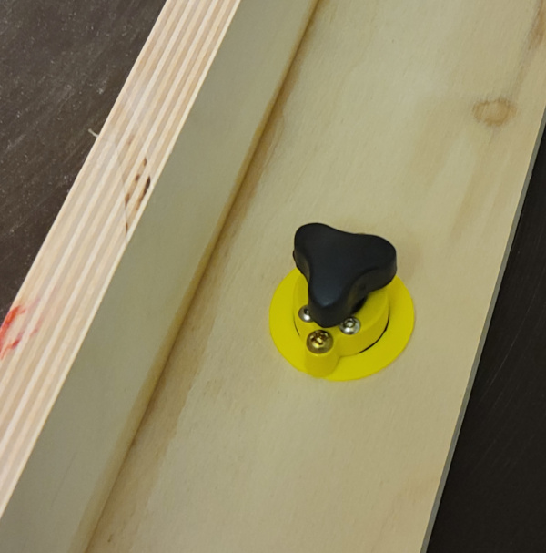
Now it is rock solid when I turn on the magnets.
Obviously a limitation is that I can't move this fence off the cast iron table top, so I can't rip really wide things, but it should be very accurate for the most common fairly narrow stuff.
Let's make a test cut and see how well I can make this fence work.
First I set the fence jig to 30mm:
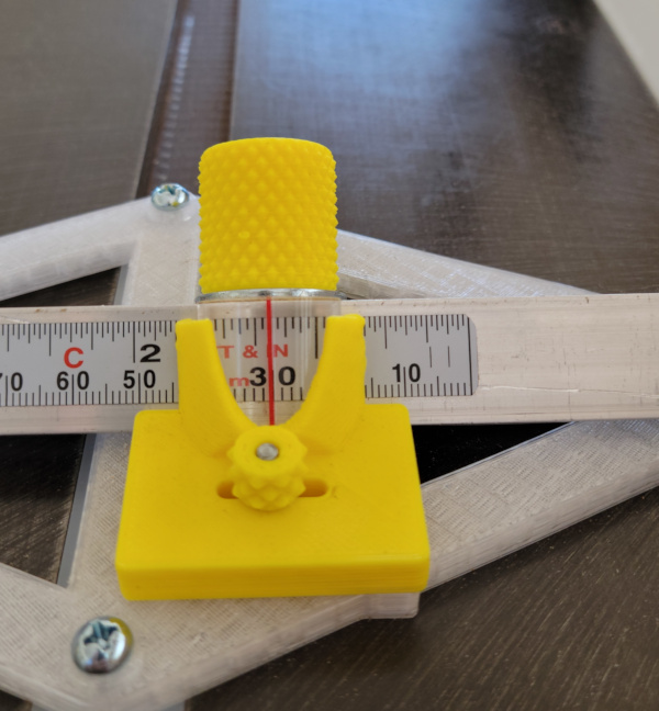
I use a position I can reproduce (the end of the blade slot in my zero clearence insert), shove the fence against the jig and lock the fence in place.
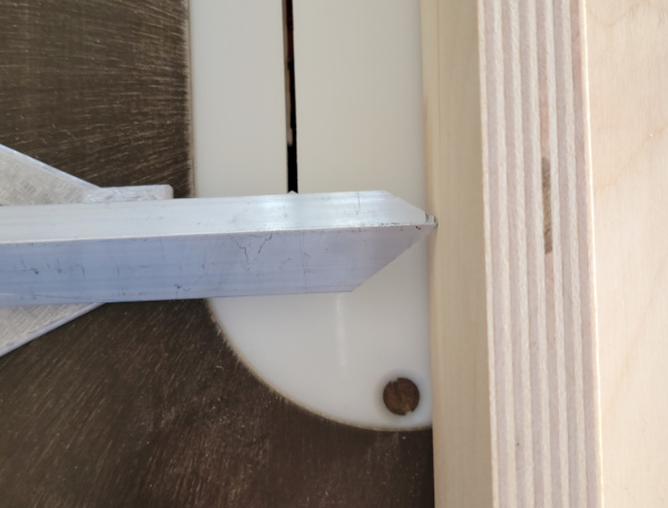
I now remove the first jig and install the 2nd at the same location, shoving the angle iron against the same spot on the (still locked in position) fence:
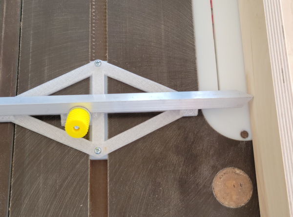
Now that both jigs are set to the identical distance, I unlock the fence and move it out of the way. I move one jig to the far end of the table, one to the near end of the table, then shove the fence against both of them, and lock it in place again:

I make the very first test cut with this fence, and put the calipers on it to see if it is really 30mm wide:
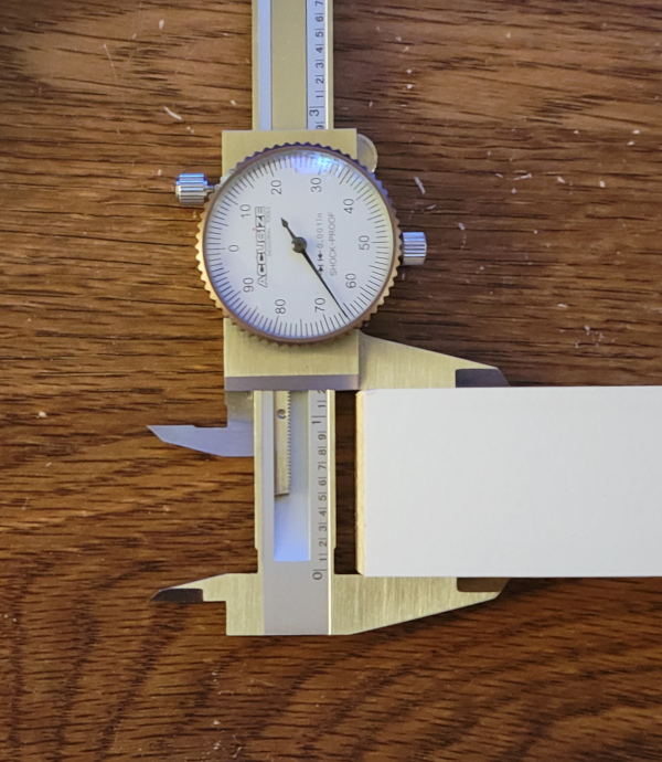
That shows 1.166 inches, which translates to 29.62mm, a little too small. Leaving the angle locked in place, I unlock the slide the magnifier is on, and try to eyeball setting it to 29.6mm. Now I can do the fence positioning again, going for a 30mm cut with the new zero position set on the magnifier:
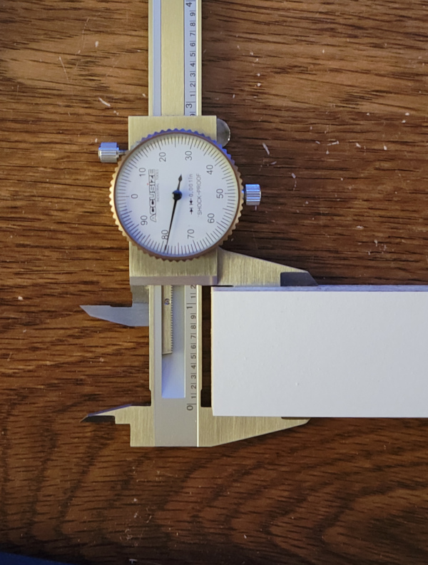
This time I get 1.179 inches, or 29.95mm. I doubt I'll get closer than 0.05mm, so that looks pretty good. I think it is dialed in now.
If nothing else, I should be able to use this fence now to build an even better fence (but not today :-).
See my other Craftsman 113 projects.