Digital Clock

This is a work in progress. A ridiculous digital clock with a (very, very) distant relationship to a Devon Tread 1.
I've digits I can print in place to form a chain that can rotate to bring one digit at a time into view. The chains for the clock will be the first thing I try to print with my MMU3 if Prusa ever decides they have it working well enough to release (followed by my order working its way to the head of the queue).
While waiting for all that, I've been reading up on how to model things in OpenSCAD for multi-color printing, and I think I have things worked out (time will tell).
The idea is to produce multiple separate models, one for each color, located in the proper geometric relationship with one another so that if the models are all loaded in the same place, they'll form the whole multi-color model. You then assign each model a color in PrusaSlicer and it does the required magic to print correctly.
So here I have the digits:

Note the tiny red dot that is part of the model and sits on the print bed so the digits will be elevated to the right height.
Here I have the chain they get merged with:
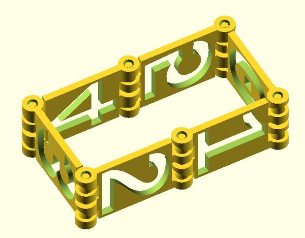
Ta-Da! The MMU3 arrived and I put it together, and my model seemed to work (after a bit of adjustment like adding a custom brim so the chain segments would stay upright, I also discovered the little dot isn't required since PrusaSlicer is smart enough not to move models you import at the same time for multi part printing):
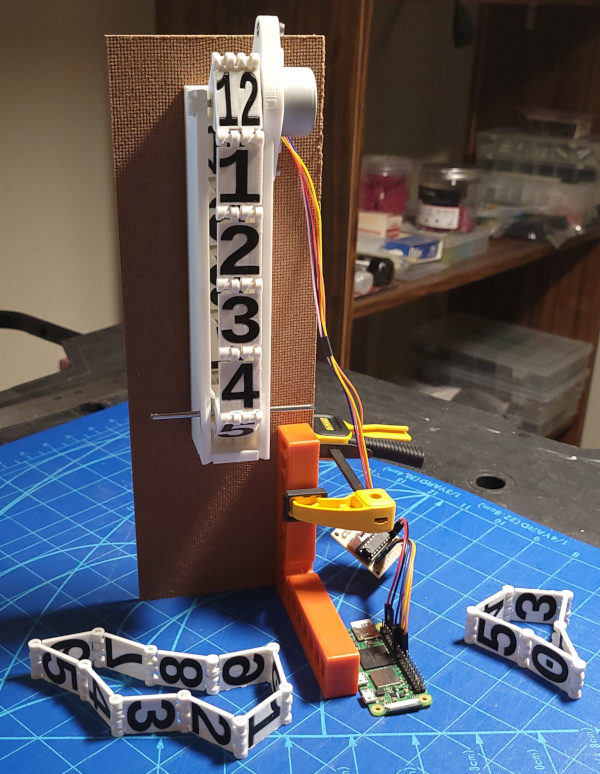
I've worn a dremel cutoff wheel down to a nub, but I got all the 3mm steel axle pieces I need cut off (and the ends smoothed with the dremel grinding wheel). I also used super glue to secure M3 nuts in all the M3 nut traps so I can screw things together without needing an extra hand to hold the nuts in place. That allowed me to temporarily assemble all three of the chains and motors so I could see how compactly I'd be able to fit them in the clock.
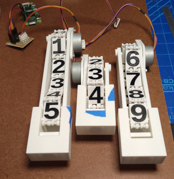
Now I've cut a piece of hardboard to mount everything and drilled the holes to mount the digits in the correct positions.
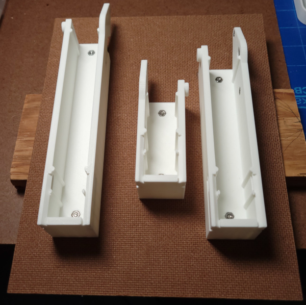
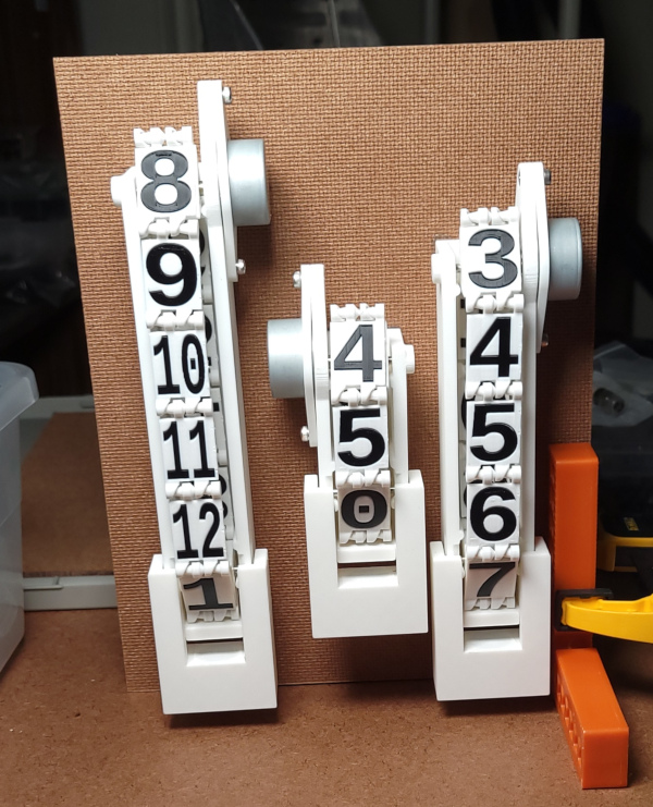
Drilled large holes to run the motor cables behind the clock and fully assembled all the pieces.
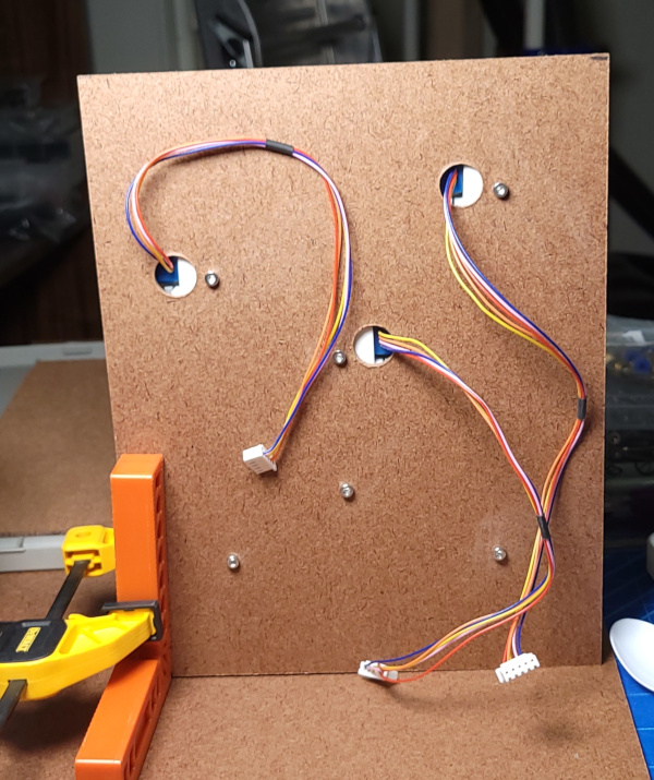
Here are the cables in the back.
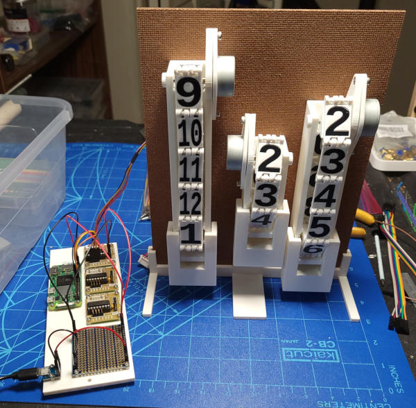
I've printed a mount for all the electronics to go on the back of the clock. I've got a micro USB port to supply power and a bus to deliver power to the Raspberry Pi and all the stepper driver boards.

It seems to work.
Consulting the Raspberry Pi GPIO pin diagram, I picked pins for the other two motors and wired everything up (reproducing Leonard of Quirm's famous spaghetti clock :-).
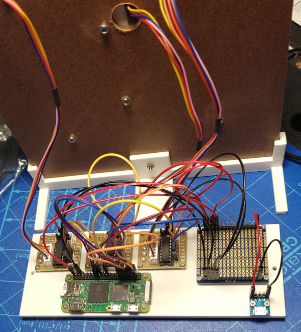
I enhanced the test program so it can talk to all three chains of digits and verified that all three operate correctly (so my spaghetti seems wired correctly).
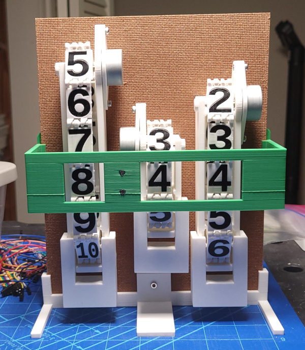
I've now finished the clock assembly. I have a clock face which hopefully indicates the digits displaying the current time while still leaving the silly mechanisms visible.
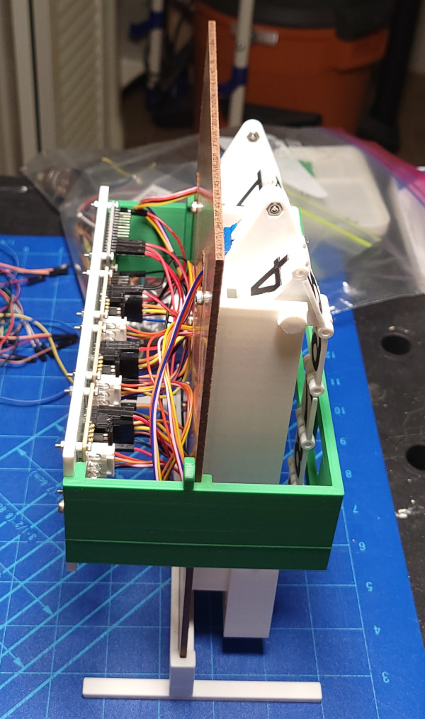
In the same spirit, the electronics and spaghetti around back are also visible.
I need to write actual time keeping code now and make it run as a service that starts on power up.