Renishaw Probe
Inspired by Touchprobe by powertomato, I decided to make a similar probe, but with mostly 3D printed parts. This is thing 805139 on thingiverse. Aside from the printed parts, the bits I bought at Home Depot were:
- 3/16 x 3/4in binding posts
- #8-32 1/2in round head machine screws
- #8-32 zinc plated cap nuts
And some random M3 screws and nuts I already had laying around.
The idea behind the renishaw touch probe seems pretty ingenious. There is an electrical circuit that is completed by running through 3 pairs of balls connected by cylinders making contact at only one point on each ball. The cylinders are fixed in a disk that "floats" with a spring holding it against the balls. A probe extends out the bottom of the disk. Virtually any movement in any direction of the probe will result in at least one point coming away from the ball it is resting against, thus breaking the circuit.
I tackled building this by designing one or two parts each evening.
Day 1: Balls and sockets to hold the binding posts so I can adjust their positions to properly make contact with the cap nuts before freezing them in place. I had to do a little drilling to make the holes big enough for the screws and file down the bottom of the balls a bit to let the screws reach the end of the binding post and secure the post, but it eventually all fit OK.
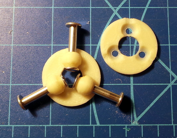
Here's how the two plates will fit together to hold the posts:
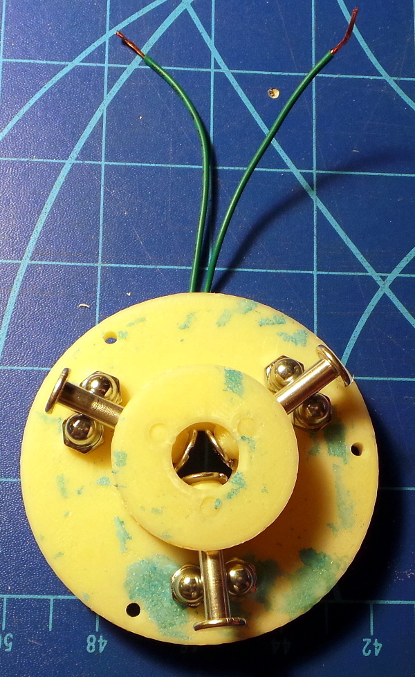
Day 2: The base plate to hold the cap nuts. I made it thick enough for the 1/2 inch screws to screw down to the plate solidly.
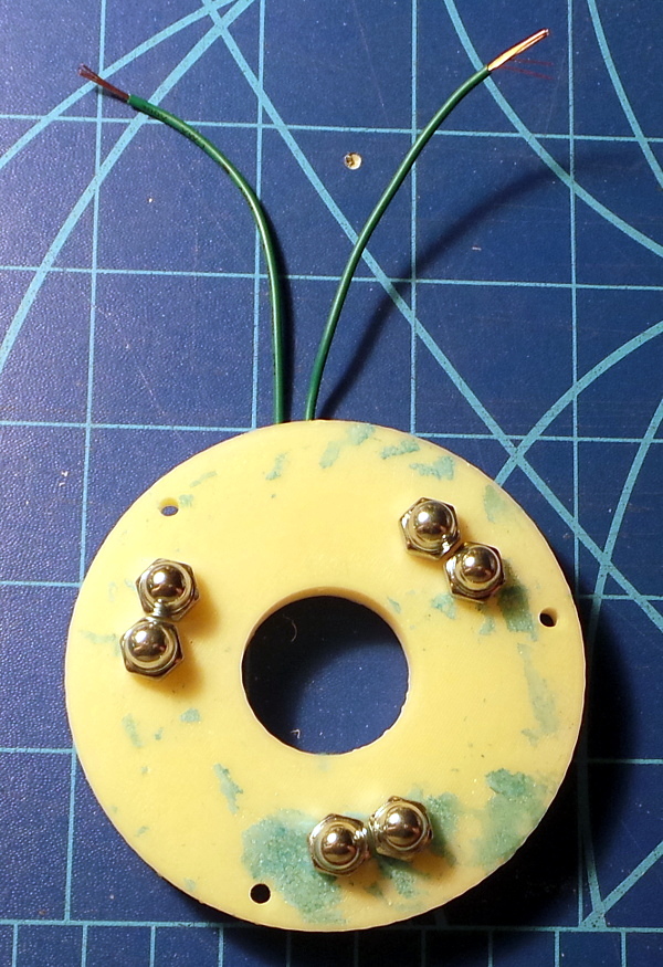
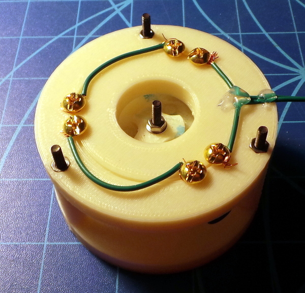
On the other side, the wires are wrapped around each brass screw before it is secured so the wires make good contact. Also printed some nut traps and M3 holes where the top of the probe will eventually be secured.
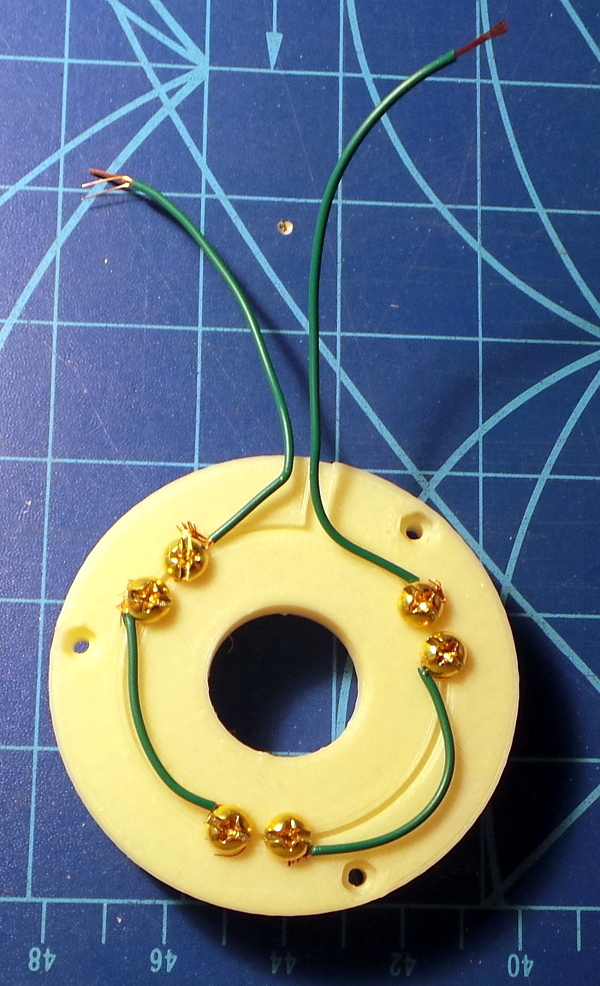
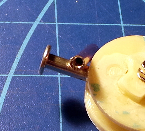
Here you see how the binding posts will touch each pair of cap nuts to complete the circuit.
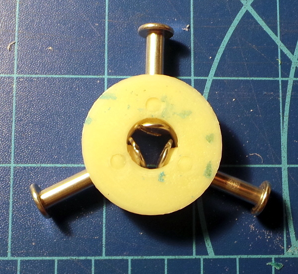
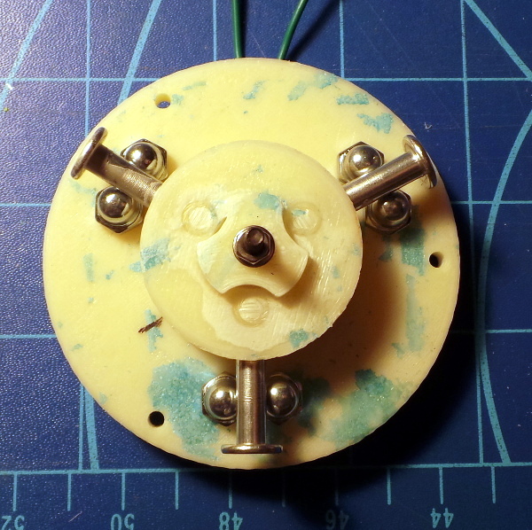
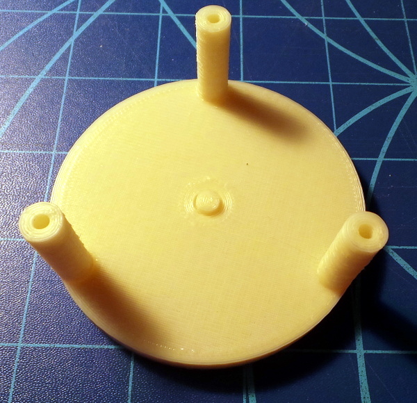
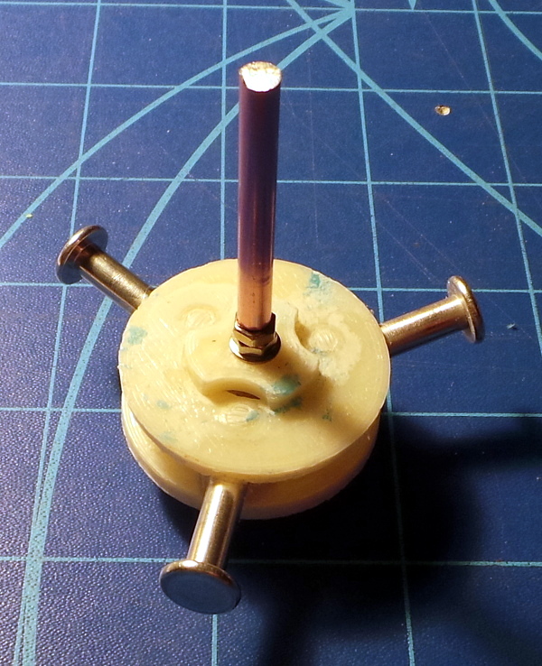
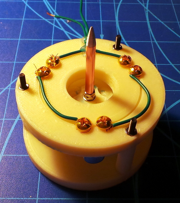
Day 3: Secure the binding posts at the right position by adding a top and bottom cap to sandwich the plates with an M3 screw to tighten things enough to adjust the posts without them flopping around. The M3 screw will also help hold one end of the spring and the other end of the screw sticks out the bottom for connecting a probe. Here's the top view with the balls now glued to the sockets (after verifying I see 5 volts running through the whole circuit once the binding post were shifted in their sockets to make good contact).
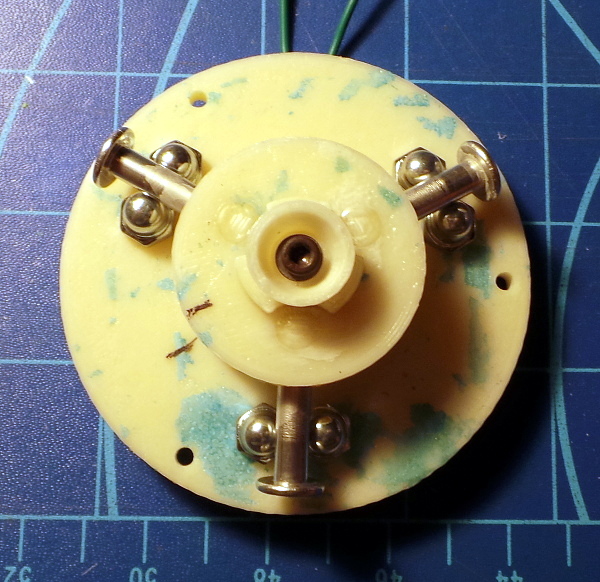
The bottom view of the part holding the binding posts with the M3 screw extending through it to provide a place to screw down a probe.
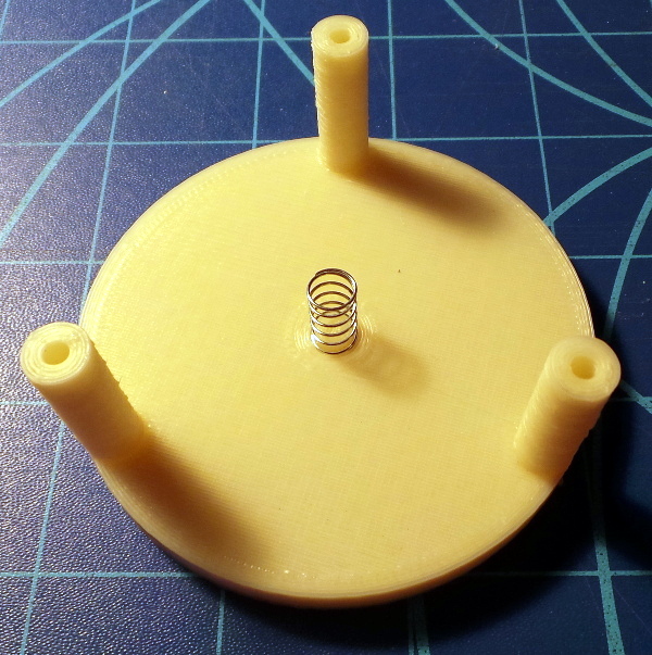
And a spring from an assortment I had which seems to fit over the head of the M3 screw nicely.
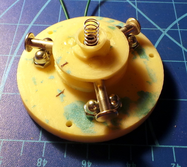
Day 4: Build the cover for the whole caboodle that compresses the spring and joins to the base.
More by luck than by design, the little center button with the groove around it grabs the end of the spring enough so I can turn it upside down and stick the other end of the spring over the top of the M3 bolt.
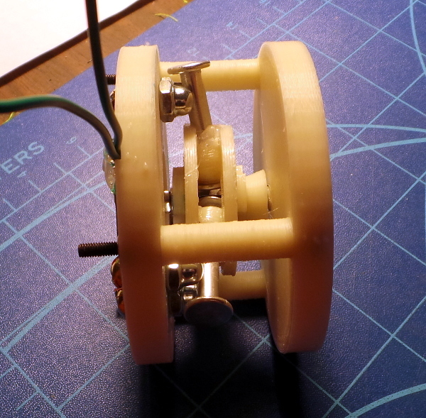
Here's the cover screwed on to the base plate.
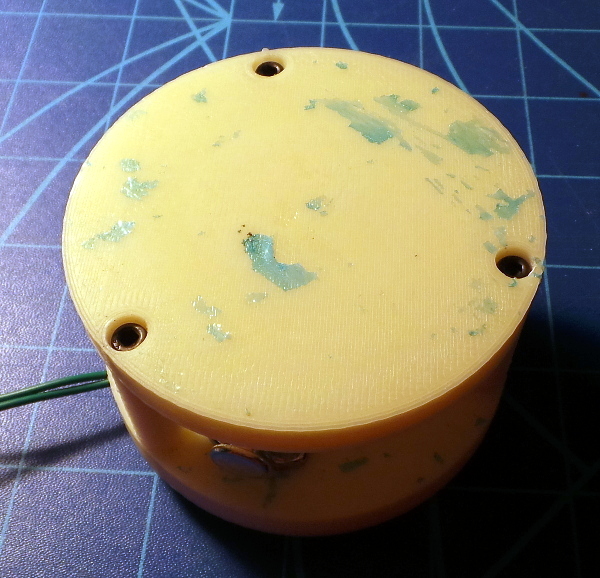
Here's the bottom view. You can also see where I used a couple of dabs of hot glue to hold the wires down.
And here's the side view showing how it all fits. You can't see it very well, but I also squished some hot glue around the binding posts which might help keep them in place better than just acetone (as long as I had the glue gun hot, I figured I might as well).
Day 5: The attempt I made to use my drill press for my Z-Axis Replacement wasn't very accurate, but fortunately I don't need accurate for the probe, I just need it to screw on by hook or by crook, so I found a piece of aluminum bar (I think it was once a knitting needle :-) and got a 2.5mm hole drilled into one end which I then tapped for M3 threads. Not exactly centered or straight, but good enough.
And it does indeed screw on to the bottom of the probe. I also found I needed to add a 2nd nut to lock the screw in place so it didn't come loose when screwing the probe on and off.
I chucked the bar back in the drill press and used a file on the other end to get a nice point, and I have a finished probe.
I tried hooking this to an arduino with a simple pull up resistor, but the circuit formed by all the ridiculous hardware (with brass screws and zinc plating and wot-not) apparently needs a much much higher impedence connection than the typical digital input on an arduino, so I've ordered some of the ever popular LM741 op amp chips and I'll see if I can cobble up something which will make the signal arduino friendly. I notice I can see the voltage with my multimeter when I run 5V through the probe, but if I try to measure the resistance of the probe with the same meter, it can't ever seem to settle on any reading.
I tried a different experiment, hooking up the same pull up resistor circuit to an analog input on the arduino, and I get different results. When I move the probe and break the circuit, I definitely see the analog input value change (it always seems to read 1023 with the circuit open), but when I release the probe, it doesn't always change back, or it changes to different values (I've seen as low as 16 and as high as 700, or sometimes it just stays 1023), so I may be having problems reliably completing the circuit solidly. Maybe a bigger spring would help, maybe polishing the posts and balls would help. I'll have to play around some (but with the voltmeter, I never saw this problem, so I still suspect a higher impedence measuring circuit would help).
Amazing! I got out the dremel and some polishing compound and hit the binding posts and cap nuts a few licks with a polishing wheel, and it does indeed seem to be much more reliable now. The analog input always went back to a small number (around 15 to 40) when I released the probe and closed the circuit, and always went to 1023 when I touched the probe. So it looks like I can detect a probe touch with an analog input pretty well now.
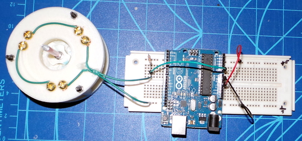
My circuit is simply a 10K resistor hooked to +5V at one end and to the A0 analog input on my arduino UNO as well as one side of the probe at the other end. The other side of the probe is hooked to ground. Here's the simple test sketch I used:
/*
  Hack modified from arduino analog input example. Reads analog
  input on input A0, prints value to serial port and turns LED
  on and off based on value.
 */

int sensorPin=A0;
int sensorValue=0;
int ledPin=13;

// the setup routine runs once when you press reset:
void setup() {
  // initialize serial communication at 9600 bits per second:
  Serial.begin(9600);
  pinMode(ledPin, OUTPUT);
}

// the loop routine runs over and over again forever:
void loop() {
  // read the input pin:
  sensorValue = analogRead(sensorPin);
  // print out the state of the input:
  Serial.println(sensorValue);
  if (sensorValue > 500) {
    digitalWrite(ledPin, HIGH);
  } else {
    digitalWrite(ledPin, LOW);
  }
  delay(1);        // delay in between reads for stability
}
And here's what the breadboard looks like:
I have now produced an alternate ball part with a smaller hole which can hold some thick copper ground wire I had in the junk pile (it measures 3.3mm in diameter). Three one inch pieces of copper replace the aluminum binding posts (and everything is secured with lots of hot glue):
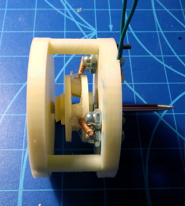
The conductivity is lots better with the copper posts. My multimeter no longer goes berserk, but can actually measure the resistance (which is now quite low, usually on the order of 1 ohm when the probe is at rest).
I modified the DigitalReadSerial arduino example code to add the LED as well as the serial port to indicate the input on pin 2, and went back to the simple circuit from the arduino example. With the copper bars, it now works perfectly - I can watch the LED turn off every time I touch the probe, and come back on when I let it go. Here's my modified sketch:
/*
  DigitalReadSerial
 Reads a digital input on pin 2, prints the result to the serial monitor

 This example code is in the public domain.
 */

// digital pin 2 has a pushbutton attached to it. Give it a name:
int pushButton = 2;
int ledPin=13;

// the setup routine runs once when you press reset:
void setup() {
  // initialize serial communication at 9600 bits per second:
  Serial.begin(9600);
  // make the pushbutton's pin an input:
  pinMode(pushButton, INPUT);
  pinMode(ledPin, OUTPUT);
}

// the loop routine runs over and over again forever:
void loop() {
  // read the input pin:
  int buttonState = digitalRead(pushButton);
  // print out the state of the button:
  Serial.println(buttonState);
  digitalWrite(ledPin, buttonState);
  delay(1);        // delay in between reads for stability
}
Time will tell if it continues to function better than the aluminum...
Go back to my main Solidoodle page.