Linksys Light Barrier
My TiVo, media PC, and MOCA link are all connected to a Linksys SE3005 Ethernet switch in my bedroom. In common with all Ethernet switches, the SE3005 is a veritable fireworks display of flickering lights, intense blue power indicators, etc. This is not something you want in a room where you are trying to sleep.
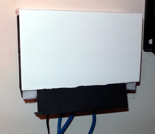
I have just finished constructing a light proof box to enclose it where it hangs on the wall behind the TV:
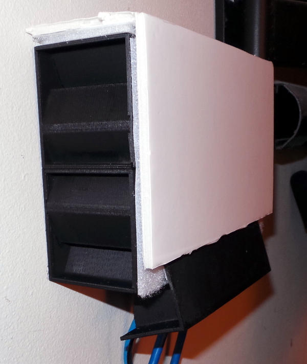
On the side, you can see the Light Baffles I used to allow air to circulate while blocking light.
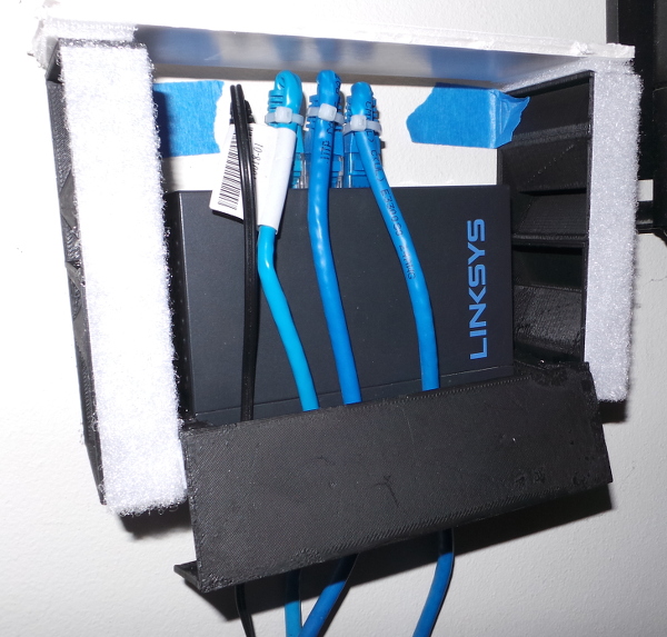
Inside the box, I've got free space for air to circulate, and wire ties on the cables to get them pointing down without pressing on the box too hard.
The complicated parts were 3D printed. The simple top and front were cut from foamboard and stuck to the box with velcro tape..
By the most important criteria this is a resounding success. Sitting in the dark long enough to get my eyes adapted reveals absolutely no human detectable light escaping from the fireworks show inside the box.
By other criteria like being a sturdy design, not so much...
I should have it mounted to the wall with anchor holes added to the very top of the light baffle boxes. That way gravity would be my friend and the box would hang down against the wall. Instead I have mounting holes on little tabs behind the switch, so I had to resort to tape to try and get it to stay against the wall at the top.
The cable guide part at the bottom needs a much sturdier mounting system. The idea was for the guide to force the cables around an angle so there would be no straight path for light to escape, but a couple of little pads of velcro don't hold it straight and instead of the cables bending, the guide bends out at an angle due to force from the cables. Something like pins that stick out of the main part and run through holes in the cable guide with a wedge to force it flat would have been better (and also making the cable guide part stronger wouldn't hurt - it is a little flimsy).
If it falls apart someday, that will be a good time to fix the design, but for now at least it does work.
For reference, here are the main openscad files that created the parts for this project:
// overall size of the linksys box
wide=121.13;
tall=75.61;
deep=26.54;

// location of the screw holes on the back surface
big_screw_hole=7.3;
small_screw_hole=3.8;
hole_depth=3.4;
hole_above_base=40;
hole_from_edge=7.55+(big_screw_hole/2);

// vent hole on the side start this far up
vent_above_base=13;

// make all walls this thick
wall=2;

// extra space around box for air
side_space=10;
slop=0.2;
above_pin_space=15;
cable_bottom_space=25;

// Height of light baffles
baf_tall=54;

module mounting() {
   rad = (big_screw_hole - slop)/2;
   translate([-wall,-big_screw_hole,0])
   difference() {
      union() {
         // Cube to hold mounting holes and pins for attaching switch
         translate([-(hole_above_base+above_pin_space-wall),0,0])
            cube([hole_above_base+above_pin_space,2*big_screw_hole,wall]);
         // Small cylinder to slide up into top of screw hole in back of switch
         translate([-hole_above_base,big_screw_hole,0])
            cylinder(r=(small_screw_hole-slop)/2, h=wall+hole_depth-slop, $fn=32);
         // Sphere to sit on top of pin and lock switch to mounting
         translate([-hole_above_base,big_screw_hole,wall+rad+0.4])
            sphere(r=rad, $fn=32);
      }
      translate([-250,-250,wall+(hole_depth-slop)])
         cube([500,500,500]);
      translate([-(hole_above_base+(above_pin_space/2)),big_screw_hole,-0.1])
         cylinder(r1=(small_screw_hole/2),r2=(big_screw_hole/2),h=wall+0.2,$fn=32);
   }
}

module back_plate() {
   // Tilt the shelf up on edge so we can attach the mounting plates on the back
   union() {
      rotate([0,-90,0])
         union() {
            // Bottom of switch rests on this shelf
            cube([deep+wall+slop,wide+2*side_space,wall]);
            // These two spacers are on either side
            cube([baf_tall,side_space-slop,vent_above_base]);
            translate([0,(wide+2*side_space)-(side_space-slop),0])
               cube([baf_tall,side_space-slop,vent_above_base]);
         }
      // Add in the mounting plates in the back
      translate([0,side_space+hole_from_edge,0])
         mounting();
      translate([0,wide+2*side_space-(side_space+hole_from_edge),0])
         mounting();
   }
}

module cylrib() {
   fplen=wall+vent_above_base+cable_bottom_space+wall;
   botlen=wall-(baf_tall-(deep/2));
   rad=max(fplen,botlen);

   difference() {
      translate([fplen,0,wall])
         rotate([90,0,0])
            difference() {
               cylinder(r=rad,h=wall,$fn=64);
               translate([-250,0,-1])
                  cube([500,500,500]);
               translate([0,-250,-1])
                  cube([500,500,500]);
            }
      translate([vent_above_base-tall,-2*wall,-baf_tall+slop])
         cube([tall+wall+slop,wide,deep+slop+wall]);
   }
}

module cable_guide() {
   ribinc=(wide-20)/6;
   rotate([0,180,0])
   union() {
      // front plate
      cube([wall+vent_above_base+cable_bottom_space+wall,wide+2*side_space,wall]);
      // tabs on top of posts
      translate([0,0,-10])
         cube([wall,side_space,10]);
      translate([0,wide+side_space,-10])
         cube([wall,side_space,10]);
      // tabs on bottom of posts
      translate([vent_above_base+wall+slop,0,-10])
         cube([wall,side_space,10]);
      translate([vent_above_base+wall+slop,wide+side_space,-10])
         cube([wall,side_space,10]);
      // bottom plate cables curve around
      translate([wall+vent_above_base+cable_bottom_space,0,wall-(baf_tall-(deep/2))])
         cube([wall, wide+2*side_space, baf_tall-(deep/2)]);
      for ( i = [0 : 6] )
      {
         translate([0,(i*ribinc)+side_space+10,0]) cylrib();
      }
   }
}
I printed one backplate and one cable_guide.
// Join a bottom and top part with glue to create a (hopefully) light
// proof baffle that will let air through. Use as building blocks to
// make a box to hold electronics that need ventilation, but have thousands
// of annoying flickering lights (like an ethernet switch, for instance).

// These parameters control the size of the block generated
//
tall=54;
wide=20;
deep=58;
rib=2;

// Calculate various baffle placement parameters from the sizes above

ratio=2/3;
a=(ratio/2)*deep;
b=wide/2;
baflen=sqrt(a*a+b*b);
bafang=asin(a/baflen);

// The basic baffle shape has a wall at one end and a zig-zag wall running
// through 2/3 of the depth

module onebaf(rb) {
   difference() {
      union() {
         cube([wide,deep,rib]);
         translate([0,deep-rb,0])
            cube([wide,rb,(tall-(rib/2))]);
         translate([0,deep*ratio,0])
            rotate([0,0,-(90-bafang)])
               translate([-rb/2,0,0])
                  cube([rb,baflen,(tall-(rib/2))]);
         translate([wide/2,deep*(1-ratio),0])
            rotate([0,0,(90-bafang)])
               translate([-rb/2,0,0])
                  cube([rb,baflen,(tall-(rib/2))]);
      }
      translate([-2*rb,0,-1])
         cube([2*rb,deep,tall+2]);
      translate([0,deep,-1])
         cube([wide,2*rb,tall+2]);
   }
}

// Take the basic baffle and subtract off a reflected and rotated slightly
// thicker baffle to make grooves in the basic baffle where two pieces can
// be joined with glue (they actually snap together pretty well, but I
// wouldn't count on that for long term use).

module bottom_baffle() {
   difference() {
      onebaf(rib);

      difference() {
         translate([wide,deep,tall])
            rotate([0,180,0])
               rotate([0,0,-180])
                  mirror([1,0,0])
                     onebaf(rib+0.2);
         translate([-1,-1,tall-2*rib])
            cube([wide+2,deep+2,tall]);
      }

      translate([-1,-1,rib/2])
         cube([wide+2,rib+0.2+1,rib]);
   }
}

// Reflect the bottom baffle to make the zig-zag into a zag-zig so the parts
// will mate into the completed baffle when joined top to bottom.

module top_baffle() {
   mirror([1,0,0])
      bottom_baffle();
}
I printed four each of bottom_baffle and top_baffle
I spray painted all the parts flat black using many coats to get complete coverage. I glued together the top and bottom baffles to make four baffle boxes, then I glued two baffle boxes together to make each side then glued the baffle box pairs to the side of the backplate. Screw it to the wall, stick velcro to everything, measure and cut the foamboard, stick velcro to it, push all the parts together and I'm done.
Go back to my main Solidoodle page.