COM2 and the Asus P4C800-E

This is the saga of quest to discover the pinouts for the COM2 header on the Asus P4C800-E motherboard. For the impatient, here are the results up front (or you can just order one):


DB-9

RS-232

IDC-10


Pin 1

Data Carrier Detect

Pin 1

Pin 2

Received Data

Pin 2

Pin 3

Transmitted Data

Pin 3

Pin 4

Data Terminal Ready

Pin 4

Pin 5

Signal Ground

Pin 5

Pin 6

Data Set Ready

Pin 6

Looking into end of DB-9 connector.

Pin 7

Request To Send

Pin 7

Looking into end of IDC-10 connector.

Pin 8

Clear To Send

Pin 8

Pin 9

Ring Indicator

Pin 9


Disclaimer: I haven't actually ordered this part from pccables.com or tried it in my computer, but the description on their web site does match the pins I eventually discovered.

On to the saga...

Note that the pin numbers of the DB-9 run across the long way, and the pin numbers of the IDC-10 run down the short way. Early on, I made the fatal mistake of thinking the IDC-10 pin numbers would also run across the long way, thus leading me to believe I didn't have the same connector described in the www.pccables.com web page as part number 07120 (the AT-Everex-Intel version). If only I had looked more closely at the pictures on that page, I would have realized my error, ordered the cable from them (once Dave Zeph pointed me to their web page) and I never would have embarked on this fun filled quest to discover the P4C800-E COM2 pinouts.

(Actually, that isn't entirely true, I guess I still would have needed to determine which of the two part numbers 07120 and 07121 I needed, but I wouldn't have had the opportunity to waste nearly so much time).

Realizing that I can control the output signals, I whipped out a silly little program to let me turn on and off the DTR, RTS, and TXD lines. With that program and my trusty 30 year old Micronta multimeter, I was able to identify the three output lines by comparing all the different pairs of signals and seeing which ones changed between + and - voltage levels when I toggled the signals with the program.

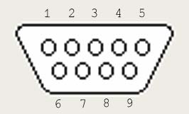
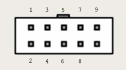
At this point, I would have had enough information to identify the correct cable if I had been paying attention, but it looked to me as if neither of the cables matched what I was seeing, so I started jumping various pins to the DTR line, then using the show comm command in Kermit 95 to monitor which signals were now on. This quickly identified CD, DSR, CTS, and RI, leaving only signal ground and receive to distinguish between. Switching to terminal emulation mode with no local echo, and jumpering the transmit pin to each of the remaining candidates, I was easily able to determine which pin was receive by observing characters echo when I type. That left only one pin, which must be signal ground since all others were identified.

(The hazard with this scheme was that random jumpering like this will at some point result in some signal being shorted to ground, but apparently the motherboard was able to survive a few seconds of this with no obvious harm).

Along about this point, I was discovering my error with the pin numbers. I think the reason I made the wrong assumption was that the cable I happened to find in the junk pile was a DTK style cable, and when I checked which DB-9 pins matched with IDC-10 holes with an ohmeter, the pins happen to match with 1 for 1 numbering if you number the IDC-10 pins the long way. The other style cable matches the pin numbers 1 for 1 if you number them the short way (which probably also explains the origin of the two different cable styles).

Anyway, once I determined the correct pin numbering and translated my incorrectly numbered diagrams (which I had to do twice before I got it right), I definitely determined that the P4C800-E COM2 header needs an AT-Everex-Intel style IDC-10 to DB-9 cable (whew!).

Having gone to this much trouble, I decided to go to a little more and do some frankensteining on the wrong cable, cutting it in the middle, and soldering the wires back together in the right order. I don't know how well the resulting cable is likely to work at high speed, but for plugging in my PDA so I can use the keyboard hack to type on a real keyboard at 9600 baud, it functions fine (I've also used a dial-up modem on it to make sure signals other than transmit and receive are working).

I'd add a picture of the result here for your amusment, but I'd probably be accused of running an obscene bondage web site (I also don't have a digital camera).

That should be far more than you ever need to know about the COM2 port on the P4C800-E (except I still don't know why Asus didn't include the COM2 cable in the Deluxe box or describe the COM2 header in the manual, but I guess we all need a little mystery in our lives - come to think of it, COM2 and the game port could easily have fit on the same bracket together).

I close with the obligatory pointer to my home page, and a mention that this page was created on September 5, 2003.

Page last modified Fri Sep 5 22:32:07 2003