|
Wherein Our Hero wastes a near infinite amount of time and energy devising ways to make cell phone rings even more annoying... IntroductionIt all started innocently enough with my plan to drop my BellSouth land line service and go cell only (since I have a cable internet connection, I don't need the phone for that). Unfortunately I found that I had to keep the cell phone with me at all times, or I couldn't hear it from across the house, thus the cell phone ring detector project was born. You can get a lot more information about background and motivation from the description of the Mark I version. (Not that I actually imagine you'd want to :-). The Mark II is a vastly improved version with more bells and whistles and better battery life (and a severe case of "second system syndrome"). CircuitsThe following circuits are presented in a logical order (unlike the way they were designed) from initial power-up to the frills tacked onto the end of the project. A less organized and more stream of consciousness version of the Mark II design can be found here, this is the sanitized and organized version. Some general changes since the Mark I include the switch to 9 volt operation (so I can just use a single battery which fits in the 9V battery compartment of the box I decided to use) and the switch to a TLC3704 voltage comparator chip (a very low power CMOS version of an LM339) instead of a LM324 op-amp. Power-Up DelayOne of the (obvious once I finally thought of it) improvements over the Mark I was the change to actually disconnect the batteries when I don't have the phone in the system, thus saving lots of battery power while I'm not at home and the phone isn't in the Mark II. To prevent accidental triggering of the detector during the initial power-up period when capacitors are charging and the photo resistor is stabilizing, I needed to make sure nothing drastic happens for a few seconds after the power comes on. This circuit does that by holding the 555 timer reset pin low while powering up. 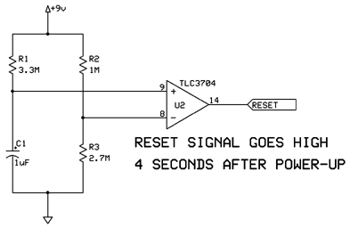
Light DetectorThe Mark I and Mark II both operate by noticing when the phone display lights up (which happens on incoming calls). The circuits are fairly similar in both, but I'm using the TLC3704 chip now, and one important change was the addition of resistor R8 to provide some hysteresis in the circuit so it doesn't accidentally trigger after the photo resistor has already been lit up and is now going back to dark. (I also needed to tweak R8 a little - after everythng was together I found the detector failed intermittently and decided I was getting a little too much feedback. The 390K value here is the final version and works much better than the initial 100K value I used in the original design). 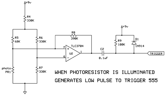
TimerI had all kinds of plans for different things to use for notification of the phone lighting up when I was planning the Mark I, but eventually settled on simulating a push of a wireless doorbell button. Since that is what I'm also doing in the Mark II, there is no need for the button to be pushed for very long, so the timing components were adjusted to give about 3/10ths of a second. The reset pin here is also where the new power-up delay circuit connects. 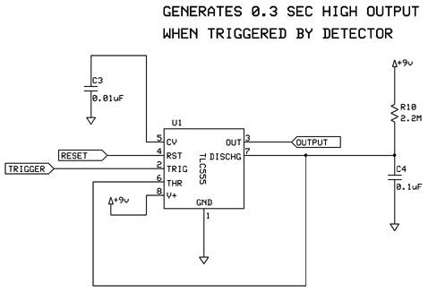
RelayNothing much has changed in the relay driver circuit, but I did add resistor R11 to prevent the 5V relay I'm using from getting blowed up by the new 9V power supply. 
MemoryNow we enter brand new territory for the Mark II. The fact that the TLC3704 had 4 comparators and I was only using 2 of them led me to seek out wacky new features I could add to use up the other two comparators. One obvious feature missing from the Mark I was a way to know if a call came in while I was gone. The first thing I need is a way to remember that single bit of information, so here is a single bit of memory implemented with some transistors to make a flip-flop (which is set by the output from the 555 timer) and one of the TLC3704 comparators to drive the memory output line from the state of the flip-flop. 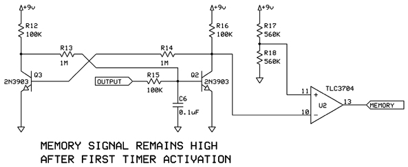
I had a simpler circuit when I was using the LM339, which I adapted from the "or-gate" sample in the National Semiconductor spec sheet, but feeding back the output as one of the inputs didn't work for the TLC3704 (apparently the power up state of the outputs is high, so the old circuit immediately turned on at power up). LED FlasherContinuing the new circuitry, the second part of missed call notification is (obviously) a flashing LED that comes on when the memory does. This is from the National Semiconductor application notes where they show how to use the LM339 as a pulse generator. I played with the resistors and capacitors till the flash rate looked reasonable (turned out to be about 2 HZ) and I ran the +9V connections from the memory output (the TLC3704 outputs provide enough current to drive the flasher just fine). Now I can find out if I missed a call without all the work of picking up a 3 oz. phone and checking the display :-). 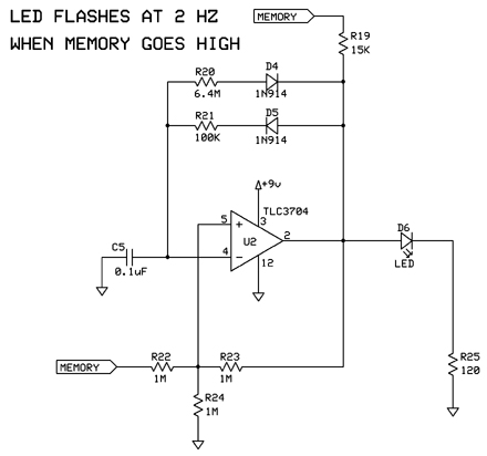
This complete collection of circuits draws about 0.3mA when just sitting there waiting to see the light. That should do much better than the mark I on battery life (in the same state, it was something like 5mA, so the mark II draws around 15 times less current). The current goes up once the LED flasher starts operating (I can't really measure it very well since it fluctuates faster than my multi-meter responds as the capacitor charges and discharges). The 4 AA batteries in the mark I lasted about a month. I hope to see much longer than a month once I get the mark II into operation. MechanicalI found the perfect box in the back room. It was an old broken down frequency counter (when taking it apart to evaluate it for this project, I noticed all the traces peeling off the circuit board, which probably explains why it wasn't working :-). It already has a little compartment for a 9 volt battery (one of the reasons for the switch to 9 volts in the design). The box (with a life size cutout of the pcboard on top) looks like: 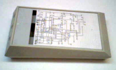
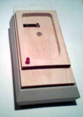
I went with a fairly simple design where the phone merely rests face down on a flat surface. The photo resistor is sunk into a shallow hole in the surface where the display light can shine on it. A short distance away on the same surface, a microswitch is mounted with a lever action long enough that the weight of the phone turns the switch on. I merely have to set the phone in place, and the switch activates the circuit, and picking it up turns everything off. The wireless doorbell is glued to the outside so I can get to the battery in it as easily as the 9 volt battery in the main box. A couple of additional holes for the led pins, and I have my flashing call notifier visible near the base of the phone. Here are the pictures of the final completed unit: 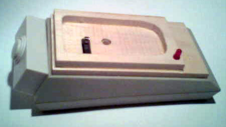
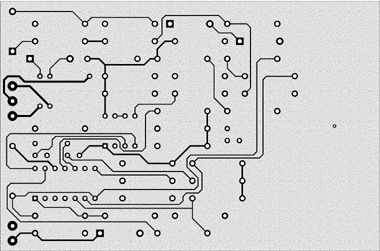
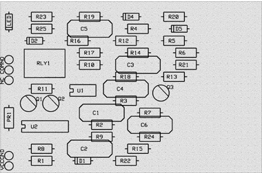
PC Board$51 (or $59 if you add in shipping) seemed too reasonable a price to pass up, so after spending a lot of time manually transferring the CadStar Express PC board layout to the ExpressPCB program, fiddling with the traces to get them just right, checking the board against the schematic and the schematic against the breadboard, I've sent off my board design to have PC boards made for me. Here's the top and bottom copper layers as well as the silkscreen (but for $51 I don't get the silkscreen actually printed on the board :-). 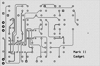
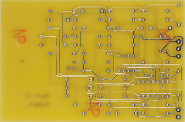
The boards showed up today, and they look just like the design. Here are scans of the top and bottom of one of them: 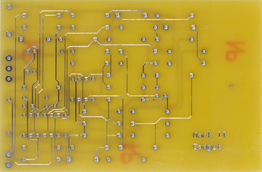
After a couple of evenings work with a soldering iron (and discovering that I had D4 and D5 backwards in my original circuit diagram - the flasher diagram above has been fixed :-), here's the populated board setup for testing: 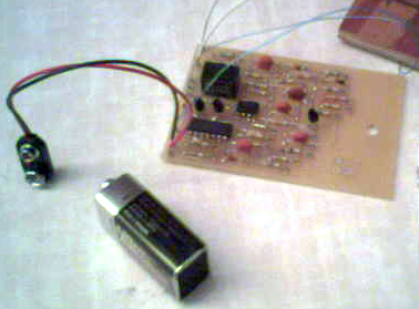
P.S. I suppose it would be just as correct to say I had resistors R20 and R21 swapped, but since I already had them soldered into the board it was simpler to reverse the diodes than unsolder and swap the resistors. This all went into service with a slightly used 9 volt battery on March 14, 2005 - the only thing left to do if find out how long the battery lasts (hopefully more than the 1 month of the Mark I design). References
|