NOTE: This is the (now obsolete) Mark I gadget. The latest and greatest gadget in this saga can be found here.
Motivation
This story started with me wanting to get rid of my landline and go with just a prepaid cell that could easily be 3 or 4 times cheaper (since I make about 5 minutes of calls a year :-).I got a Virgin Mobile phone to see how the plan would work, and it quickly became apparent there was a flaw. If I don't actually tote the phone around with me everywhere, I can't hear the ring tone (especially with the television on).
I started a search for a ring tone amplifier (or some such gadget) that would work with my phone, and while there are upwards of 4 billion hits for regular phones, it quickly became apparent that no such thing seemed to exist for cell phones (unless you want to count all the movies where terrorists set off bombs using cell phones, but blowing things up seemed like a bit more notification than I wanted even though I have no doubt I can find cell phone detonator plans on the internet more easily than cell phone ring amplifiers - but before the FBI comes around, I hasten to add that I didn't actually look :-).
I did find this pen/cell phone ring detector, and started thinking about hacking one apart to get to the signal that lights the LED. It then occurred to me that it would be nice to keep it in working condition so I could use it more normally sometimes, and I thought about just detecting the LED flashing. But I soon realized, my "Flasher V7" phone (otherwise known as an Audiovox 8910) has a front display with a backlight that comes on when there is an incoming call, it seemed obvious that one way to meet my criteria for a ridiculous ring detector would be to notice the phone display lighting up and forget the pen detector. For fun, I got one of the pens anyway, but the range is not too good. Anything more than about 2 inches away, and the pen detector doesn't notice the phone. Even with the phone and the pen in my shirt pocket, the phone can be too far away to set off the pen. With both the phone and the pen next to each other on the desk, I also noticed that sometimes the pen goes off for no apparent reason (I guess the phone is contacting the cell tower or something). I'd definitely put the pen in the category of a novelty, not a particularly useful item.
Electronics
Anyway, since idle hands are the devil's workshop, and when I'm on vacation I try to be as idle as possible, I soon found myself poking around among the electronic junk in my back room and asking myself: "What is the most ridiculous possible way to build a ring notifier with the junk I have lying around here?"I found a small photocell and an LM324 op-amp chip. Even more dangerous, I found an application note for the LM324 showing how to use it as a photocell amplifier.
I envisioned a small box with a cradle I could leave the phone in while I'm at home with my Rube Goldberg light detector built into it and some sort of contraption to make lots of noise (but not an explosion) when the phone lights up. Another advantage is that I'll always leave my phone in the same place, so I won't forget where it is. If I keep the gadget near an electrical outlet, I can plug in the charger too. (So I clearly need to design the cradle to leave room for the hole in the phone where the charger plugs in - something to remember if I get that far).
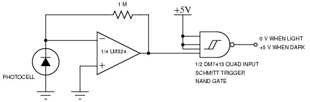
Anyhow, before I can get finished, I have to get started. I dug my trusty breadboard rig out from under several layers of junk, started plugging in wires, and was soon able to demonstrate that the sample op-amp circuit really did work. I could hide the photocell under a little cap and get a few millivolts output, or remove the cap and get 3 or 4 volts output on the other side of the op-amp. All very nice, but I'm going to want to use this to switch things on and off, so a nice true/false kind of signal with square edges would probably be more desirable. A little more scrounging around the back room came up with a 7413 schmitt trigger nand gate, and gave me the first chunk of my circuit:
The square edges are nice, but I'm going to want to make noise long enough to notice once the phone lights up, and I'll want to "debounce" any effect of flickering light, not to mention that the Rube Goldberg principle requires me to add extra circuits even if they turn out not to be needed. Since my junk pile includes a 555 timer chip, and since the trigger for a 555 timer is a negative going edge, and since that's what comes out of my nand gate, the universe is practically demanding that I throw in a 555 timer circuit to stretch the signal out and invert it back to a +5 while I'm at it (there may also be a federal statute requiring all hobbyist circuits to include at least one 555 timer chip :-). I also happen to have some big capacitors lying around from repairing an old motherboard a while back, so they are the ideal candidate to give me a nice long signal from the following 555 "monostable" timer circuit:
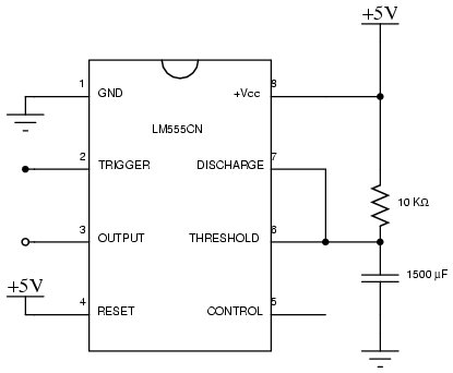
If I hook the output from the schmitt trigger in circuit 1 to the trigger input of the 555 in circuit 2, I get a little less than 20 seconds of steady +5 volt output from the output of the 555 when the photocell gets lit up (however briefly). I didn't pick 20 seconds - it picked me. I just plugged in random resistors together with the 1500 uF capacitor I happened to have until what seemed like a reasonable time showed up. No doubt a smaller capacitor and bigger resistor could achieve the same thing with less energy drain, but this was the first combo that worked well for me.
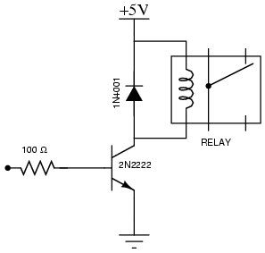
I still don't know what I'm gonna make noise with, but all this time I've sort of had the idea I'd like to use an old-fashioned electro-mechanical bell and clapper (just a small one - not an 18 inch fire alarm bell or anything like that). If I go with something like that, I'll obviously need to trigger a relay. My junk pile failed me on relays, so I bought a small 5 volt relay at Radio Shack (part number 275-240). Perhaps the 555 could drive the relay directly, perhaps not, but with some 2N2222 transistors lying about back in the trusty junk pile, why not add a relay driver circuit while I'm at it?
Adding this additional junk to my breadboard demonstrates that it also works. I can hear the relay click (and watch the resistance go from infinite to zero) when I light up the photocell, and 20 seconds later it clicks off. If I wait till it is dark outside and turn off all the lights, I can even demonstrate that the thing clicks on when I light up my cell phone and hold it over the photocell (a good thing after doing all this work). Unfortunately, a relay click is even less audible than the ring tone on the phone. It is time to search for my ideal noise source.
I go online to places like homedepot.com, no old fashioned bells. I expand my search with google and find several bells that are just what I want if only I lived in Great Britain. I check a few local hardware stores, but no dice. Apparently, metal clanging on metal is no longer appreciated in the United States :-).
My first choice denied me, I just wandered about the local Home Depot keeping my eyes open for ideas, and I spotted the collection of wireless doorbells they sell. The kind of bell I wanted to use has sometimes been used as a doorbell. A doorbell should be designed to be loud enough to hear, and closing a relay is a lot like pushing a button, so I ought to be able to hack the push button to substitute my relay (if I'm careful and don't break it completely). The wireless doorbell has the additional advantage that I can keep the noisemaker in one place (near the center of the house so I can hear it from anywhere) and the phone gadget somewhere else (closer to where I'm likely to be sitting if the phone rings). I decide to buy the model with 64 different tunes (on the off chance that at least one of them won't be utterly insipid) and the dual buttons (for front and back door), so if I break one, I'll have another to hack after getting practice in what not to do.
I get it home and take apart one of the buttons, and find myself mystified. The actual button is a little black cube with 4 leads. What kind of push button needs 4 leads I wonder? Nevertheless, I start poking around with a piece of wire, and determine that shorting out either pair of diagonally opposite leads on the button results in the doorbell chime going off. I don't even have to break anything because there is enough lead sticking out that I can just solder a couple of small wires to one pair, and leave everything else in the button assembly undisturbed. Having added my wires to the button, I plugged them into the breadboard across the normally open relay connectors, removed the cover from the photocell, and "Dong!", my wireless doorbell went off! Once again, I waited till dark, and tried it with the cell phone backlight, and once again, the doorbell went off. I had successfully constructed a hack that could tell me when my phone rings!
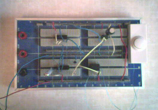
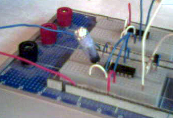
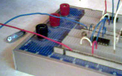
Since this is a camera phone, I might as well take some pictures of the setup at this point. This is final breadboard with the doorbell wired into the relay:
This is a close-up of the photocell with the improvised cover in place (a small piece of tubing with some foil taped over one end:
And here is what the photocell looks like without the cover:
Mechanical
Now, before I can declare my independence from Bell South, I need to turn the breadboard into a finished product. I'll have to rig some kind of cradle for the phone that excludes ambient light and just illuminates the photocell with the phone display backlight. Thinking about it, I also realize that I'll want to make sure the system is deactivated when the phone isn't in the cradle, or it will probably be going off all the time I'm trying to talk. Probably will want to have an "arming" switch to keep things quiet when the phone isn't in the cradle (any kind of microswitch to notice the phone in the cradle is probably getting too ticky for me). From electrical engineering, I need to move on to mechanical engineering if I am to produce a fully functional gadget.All sorts of silly ideas swirled through my head. One of my favorites was getting a couple of pieces of nesting pipe that I could rotate to close up the hole I drop the phone in, but any kind of hole I drop the phone in is always gonna have a problem with the charging cable getting in the way. In the end, I decided a simple form fitting depression I could lay the phone in face down should work if I have something like a felt or soft plastic gasket to fit around the face closely and keep out ambient light. That would leave the tail end of the phone exposed (not to mention the antenna) so I could plug in the charger easily. Even this simple idea leaves room for flights of fancy. Could the phone stand the heat in a vacuum form machine to make a mold of the face? (If I could find a vacuum form machine). Could I do a plaster cast? How about painting it with wax to make a mold for a lost wax casting of the perfect cradle in bronze? All very silly. In the end I realized the simplest available low tech custom molding technique is good old fashioned paper mache (Hey! Grammar school arts and crafts actually comes in handy... :-). A little plastic wrap to protect the phone from wet paper and glue, and I should be able to produce a nice tight fitting mold to keep the light out in no time. If I glue a some cardboard ribs to it, it should be stiff enough to support the phone.
Here's the result of five or six layers of newspaper and watered down carpenter's glue, not yet fully dry or trimmed:
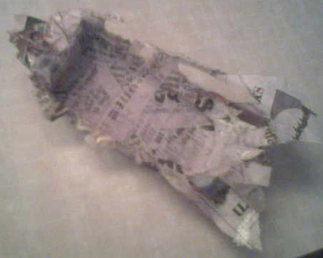
I'll give this overnight to get fully dry, but I should mention that one of those new Glad disposable plastic containers makes a great thing to mix paper mache paste in (as long as you have lots and lots of newspaper around when it splashes).
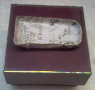
Anyway, here is the shell dried and trimmed sitting on the small plastic box I found that should hold everything after a bit more mechanical engineering:
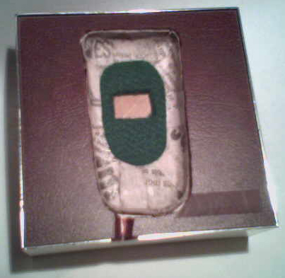
And here we have the box top cut out, the shell mounted, and a felt pad added to help cut off the light. Also added a groove to the top of the box so there is room for the charger plug when the phone is in the shell:
Lesson
So, everything is finished, the circuit board all soldered up, everything in the box, completely done! Unfortunately, it doesn't work. Even though I was able to make it work by pointing the phone at it at night, clearly the conditions are different in the actual box as constructed. Measuring the output from the op-amp with the phone in the shell shows the voltage barely flicker when the backlight is on, and it never hits anything like the level needed to trigger the rest of the circuit. The lesson is that I should obviously have constructed the shell and tested the photocell with the phone under actual conditions before committing to the whole design.Obviously it is time to see about a different detector, which perhaps I can wedge into my existing circuit without too much trouble (since a minor mod to the board would be a lot simpler than building a new one).
Another component I had in my junk pile when I started was a photoresistor which has almost as big a face as the display on the phone. Perhaps I can adapt things to use it. The first thing to do is make some experiments to see what sort of performance I can expect. Wrapping the phone and the resistor in several layers of black plastic trash bag with just the resistor leads punched through reveals that the resistor does a very impressive imitation of an open circuit in absolute darkness, and then drops down to about 80K ohms when I turn the phone light on. That's the best I can expect, but to avoid making the same mistake again, I should try the resistor in the shell I already have. I just need to make a couple of small holes for the leads to fit.
Did that, and I'm impressed. With the phone plugged tightly in the shell, I once again get something that looks like an open circuit. Even when I shine a powerful flashlight around at in various different directions, I still stay at least 2 M (and for that the light has to come from under the shell - an unlikely direction for light to leak in if the box is closed.) When I turn the phone light on, the resistance drops to about 280 K (which isn't as low as the plastic bag experiment, thus demonstrating the value of real world tests).
If I don't plug the phone in tight (which is a little difficult since the shell got stiffer after everything was epoxied into the box), the resistance is about 2 - 4 M with the phone just sitting on top blocking most of the light. When I turn the light on, I get about 290 K, so there is still a large change in resistance with the light on or off.
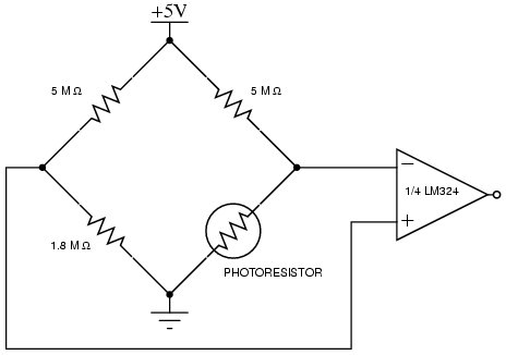
Now I just need to figure out how use this resistance change to translate into something that I can feed the op-amp without a lot of changes in the rest of the circuit (Oh No! I need to understand a little bit about what I'm doing!). I dredged up distant memories of a wheatstone bridge being used to measure resistance changes from EE classes, and looked it up on google to refresh my memory. The LM324 can be used to amplify a voltage differential, which is what I'll have across the center of the bridge, and that voltage will vary if one of the arms is the photoresistor, so I may have a way to salvage most of my existing circuit board. Breadboarding up the wheatstone bridge circuit (this time with the photoresistor actually mounted in the shell and in the breadboard circuit so I can test under actual conditions), I come up with the following substitute detector:
The breadboard circuit successfully generates a large enough voltage to trigger the schmitt trigger when the light is on, and sits there at almost zero with the light off. I even tried shining a flashlight around, and no false alarms. Time to add the resistors to the circuit board and wire in the new detector.
Unfortunately, when actually connected to a schmitt trigger chip, the LM324 doesn't work (instead of about 5 V output I see about .6 V). My feeble brain obviously doesn't understand something about the characteristics of the 7413 chips. So, forget the 7413. I yanked it out of the socket, and ran some wires to the breadboard (plugged into the pins of the old 7413 socket) and hooked up a regular old 7400 nand gate chip. By golly, that actually works right (well, "right" might be a little strong, but it does function as desired anyway).
So, with the phone in the shell, if I turn on the light, the relay triggers as expected. I also tried plugging in the phone charger, and verified that the little red LED that lights up while the phone is charging does not trigger the relay (which is a good thing, as I wouldn't want the alarm to go off just because I am charging the phone). I think my third variation actually works OK. Now all I need to do is desolder all the leads to the 7413 socket and convert it to a 7400 socket by reconnecting things appropriately. (No doubt this whole process would be much more efficient if I knew what I was doing :-).
While I was playing with this, I also measured the current this whole thing draws, and it appears to be around 5.5 mA normally, and 130 mA when the relay is active. Since Duracell's web site has a graph of typical service hours with the lowest load being 10 mA, I guess 5.5 isn't too bad. I'll see how long the batteries actually last in practice.
After getting everything put together, the circuit board modified, and all pieces soldered in (testing very carefully at each stage), I learned one more lesson: Cadmium sulfide photoresistors are really really sensitive to heat! The very last thing I did was shorten the leads to the photoresistor and solder them on. Apparently I killed the photoresistor during the soldering (that probably explains why they have such long leads on them). Fortunately, I had another resistor around, not as big, and the resistance doesn't drop as much as the original one, but it still works fine with the rest of the circuit. I soldered it at the very tip of the leads, and added a big alligator clip as a heat sink while soldering. Fortunately, I got this one in without destroying it.
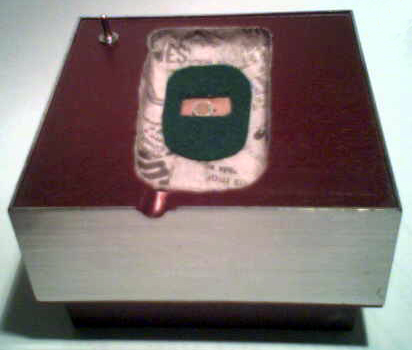
So, it is all finished (until I decide I want to make more mods). Here's the finished box:
and the box opened to see the circuit board:
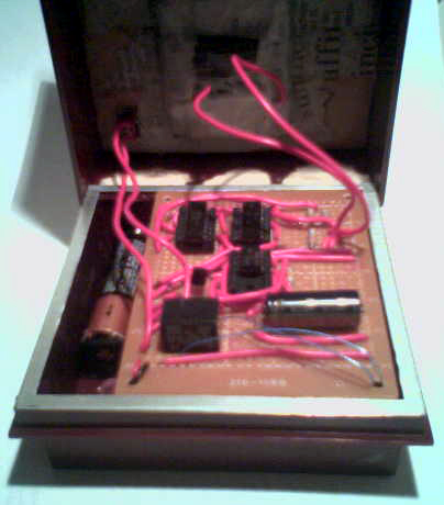
and the circuit board lifted to see the battery and doorbell remote hidden in the bottom compartments of the box:
Things To Do
The most obvious flaw with my current design is the location of the "armed" toggle switch in the circuit. I put it on the relay to prevent it from triggering when the circuit is disarmed (which is good to do when the phone isn't in the box, otherwise it is going off all the time). The problem with this is that the 555 timer goes off anyway, so if I flip the switch to armed soon after putting the phone in, it sounds the doorbell anyway. I should have put it in series with the photoresistor. That way, when it is disarmed, it would look like an infinite resistance was in place (i.e. total darkness), and I wouldn't need to worry about anything else (that would also probably make sure the minimum power is being sucked from the batteries when it is disarmed). [Actually, I went ahead and did this - it was too simple for too much benefit, and it does work much better now].Adjusting the 555 timer would probably be good as well. My original plan of running a bell needed the 20 seconds, but for just simulating pushing a doorbell, something like 1/10 of a second would make more sense (and draw less power in the long run). If the time were shorter, I probably wouldn't notice the arming switch problem either.
The box also needs work. It is just hinged at one edge, so if I'm not careful, it falls open when I pick it up. I need a pin or a screw or something to hold it closed better. It might be nice to keep the circuit board and battery holder from rattling around so much as well.
Of course, all these adjustments reduce the fundamental Rube Glodbergness of the device, so I'm leaving it as it is for now.
References
By the way, in case you are wondering, the circuit diagrams were generated with xcircuit and the postscript file it produces was rendered into a jpeg image with gimp. All running on a Fedora Core 3 system (Gimp comes with fedora, and xcircuit only took about 10 minutes to download, build, and install). The photos and sound file were downloaded off the phone using bitpim with a cable for a LG-VX6000 from Radio Shack and USB drivers from futuredial.com.Also in case you are wondering why the circuits make no sense, I'd just like to say I have no idea what I'm doing. These are just the results of cut & paste operations from bits of circuits I found in books or on the internet interpolated with dim memories of various EE classes from long ago (though not far away - they were just down the road at FAU :-).
And, as long as I'm giving links, I obviously need to take this opportunity to point you at my home page where you will find earth saving political ideas as well as ways to keep your computer's clock set right :-).