Solidoodle Calibrations
This page is the calibration I did on the original solidoodle. Now that I've made the radical change to a Titan/Aero hot end, I'm doing new calibrarion.
Bed Level
The printer never really worked well at all until I built the Dial Indicator Rail Mount. This is a painful device to use since you have to keep taking it off moving the carriage and putting it back on in a different place, but using it, I can finally get the bed pretty much perfectly level, especially if I take the time to make several new sets of measurements after I turn the leveling screws. After a few passes at 3 spots around the bed, I get it reading the same value in each position, and now I'm level (and, fortunately, it seems to stay level until I deliberately do something that will change it).
The procedure in gritty detail is:
- Move bed down far enough so the dial indicator won't touch it.
- Move carriage all the way to the right and up near the front.
- Put railmount (holding dial indicator) on the left side so the tip is pointing towards a spot near the front left leveling screw.
- Raise the bed till the dial indicator touches and reads something like 2mm. Make a note of the Z level value in RepetierHost as well as the exaxct reading on the dial indicator.
- Lower the bed so the dial doesn't touch any longer.
- Take the railmount off the rails and reposition it to a spot near the center of the rails.
- Move the carriage back till the tip points near the rear leveling screw.
- Raise the bed to the same level it was at previously.
- Turn the rear leveling screw till the dial indicator reads the same as the previous value.
- Lower the bed so the dial indicator no longer touches.
- Move the carriage back to the front again.
- Remove the railmount.
- Move the carriage all the way to the left.
- Put the railmount back on the rails on the right side so it points near the front right leveling screw.
- Move the bed back up to the same position.
- Turn the front right leveling screw till the dial indicator reads the same value again.
- Tilting the bed at different spots has now changed the value you'll read at other spots, so keep doing this whole procedure till the amount of change is so small that all three points read the same (to within a teensy amount, anyway :-).
Extruder Steps
You want to be sure the extruder really eats 10mm of filament when you tell it to extrude 10mm of filament. I used the Extruder Calibration Tool V2 from thingiverse to do this.
You heat up the extruder and clip the small piece to the filament, then run the tall piece through the slot and place it on top of the carriage so the filament runs parallel to the length. At this point, you can measure the exact distance from the small piece to the base of the tall piece with a caliper. Now slide the tall piece out of the slot, leaving small piece clipped to the filament, and manually extrude something like 40 or 50mm of filament.
Put the tall piece back in the slot, and measure the distance from the base again, and it should agree with the amount of filament you extruded. If it doesn't agree, compute the ratio and change the eeprom setting for the extruder steps per mm based on the ratio (if you extruded less than expected, make sure the ratio you compute has the biggest number on top, and vice-versa).
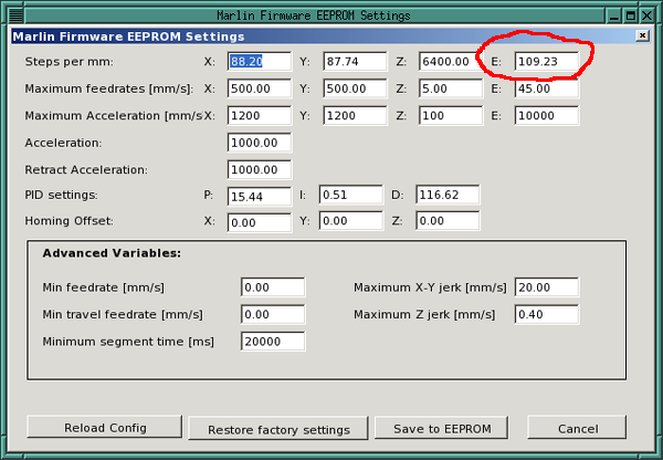
Here's the dialog with the extruder steps per millimeter circled in red:
Z-Stop
Once the bed is level, you want to get the Z-Stop screw adjusted so the first layer will print at the correct thickness. The Z-Stop with Nut Trap is a handy mod to make this adjustment stick where you put it rather than vibrating loose over time.
I generally do this adjustment in a couple of passes. First I screw the Z screw down so I know the bed will stop well below the nozzle. I then use a thin brass shim I have (a piece of paper would probably work as well), putting it under the nozzle and hitting the Z Home button in RepetierHost. If I can slide the shim out from under the homed bed with no resistance, then the bed is stopping too early, so I lower it again, back off the Z screw a little, then try homing again.
When I can just slide the shim out against a little resistance, I've made it through the first coarse calibration.
Now I crank up the printer, get the bed heated, and print a single wall, single bottom layer, calibration cube (see next section). I examine the bottom layer. What I want is a water tight layer where all the lines joined together and there are no gaps. To get there, I might need to lower the Z screw a bit till I get a cube printed that does show gaps. Now I know the bed is stopping too soon, and I want to raise the screw just a tad to get the bottom water tight again. As soon as I sneak up on that level, the Z level is set correctly (or as correctly as I've ever been able to get it, anyway).
 |
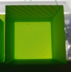 |
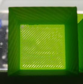
| Not quite right | After 1/4 turn |
|---|
I'm telling slic3r that the first layer is 0.3mm, and if I put the calipers on the brim printed with the cube on the right, I get 0.29mm, so that's pretty close to 0.3 and makes it seem like the first layer setting is correct.
Filament
Handily, the calibration cubes being printed for adjusting the Z-Stop is also useful for filament calibration. I use this openscad source to make a cube that is about one inch square, but is rounded to an exact multiple of the extrusion width:
// Make a calibration cube that is about 1 inch in every dimension,
// but round it to an exact multiple of the wall thickness we are aiming
// for (just to be picky).

// Note: Use slicr3 and the .3mm-flow saved settings to print.

want_x = 25.4*1.3;
want_y = 25.4*1.3;
want_z = 25.4/2;

wall=0.48;
layer=0.3;

xwalls=round(want_x/wall);
xside=xwalls*wall;

ywalls=round(want_y/wall);
yside=ywalls*wall;

zlayers=round(want_z/layer);
zside=zlayers*layer;

cube([xside,yside,zside]);
Since I have a 0.4mm nozzle, the consensus on the soliforum site seems to be that I want an extrusion width of 0.48mm (hence the wall=0.48 in the openscad file.)
When I print the resulting cube, I tell slic3r to print with 1 layer on the bottom, 1 layer perimeters, and zero layers on the top and 0% infill. That prints an open box which should have a wall thickness of 0.48mm if all is adjusted correctly.
Since every roll of filament (especially from different sources) is likely to have slightly different diameter filament, I measure the filament with calipers in at least a half dozen places and average the readings. I can then plug this into a filament definition in slic3r and save it with the name of the filament roll ("Octave green", "Solidoodle black", etc). That way I can just choose the right filament definition when I use that roll again.
If you have the right filament diameter set in the slic3r filament definition, but the calibration cube doesn't print walls exactly 0.48mm thick, you can tweak it by adjusting the extrusion multiplier setting as well.
Once you get 0.48mm walls, that filament definition is dialed in, but be sure you go to the advanced screen in the printer settings and set all the expected extrusion widths to 0.48mm as well (especially since the solidoodle default definitions all say 0.42mm to go with the old 0.35mm nozzles).
X-Y Steps per millimeter
This is important to get right if you are planning on printing parts which need to be an exact size, otherwise it comes out the wrong size with bolt holes in the wrong place, etc.
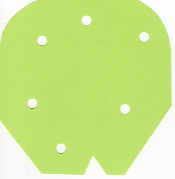
There are various "nickle" calibration files on thingiverse that check this, but they are too small to notice a small variation which will have a large effect across a large object, so what I did was get some fairly thick paper and cut out a somewhat random shape that was about 100x100mm to take up a large chunk of my 150mm print bed. I punched some holes in it as well then scanned it into my computer using a flatbed scanner at 600DPI:
I poked at it with gimp till I got a nice 2 color black and white version with just the silhouette of the shape in black. I then imported it into inkscape (hint: inscape insists all images are 90DPI no matter what the metadata says, so after the import I had to scale the size by 90/600 to make it be the same size it started as).
Using the inkscape trace bitmap tool, I turned it into a "path" rather than a bitmap, then I used the inkscape to openscad extension to turn it into a openscad file extruded 0.9mm thick (3 layers if printed at 0.3mm resolution). I then printed that object:
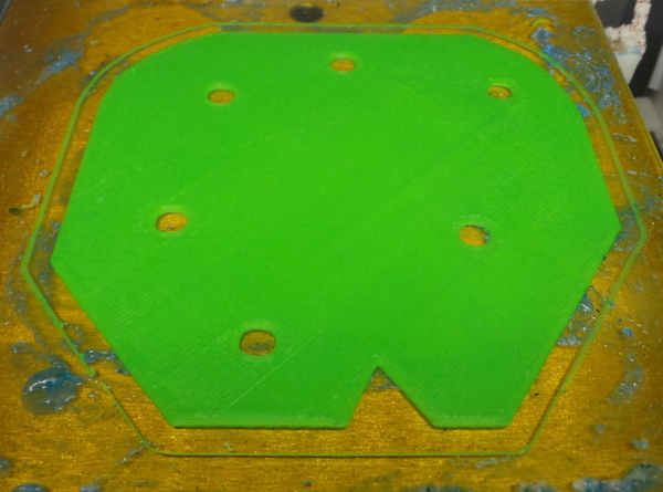
I compared it to the original paper cutout:
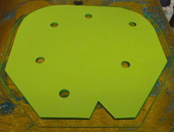
That's not a good angle, but if I peel it off the bed and hold it up to a light, it really does match pretty much exactly.
If it hadn't matched, I'd have needed to scan the printed part and compare it with the original scan in gimp, picking off positions of holes and things to see how far off it was in X and Y and adjust the X and Y steps per millimeter in the eeprom settings. (I did that previously when printing My Electronics Cover, so it is good to know the settings are still accurate.)
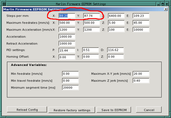
Here's the location of the X and Y steps per millimeter values in the eeprom dialog:
VREF
I keep thinking I ought to check my motherboard VREF values, but worry about shorting something out. Perhaps I'll design a special cover to go over the trimpots with wires I can use to access the specific points I need to check.
Cylinders
I've done some (not too successful) calibration experiments in Fun With Cylinders.
Go back to my main Solidoodle page.