MK4 Camera Mount
Build mount for a Raspberry Pi Zero W plus camera to be mounted on the wire shelf next to the MK4 to get it away from all the vibration on the MK4 table.
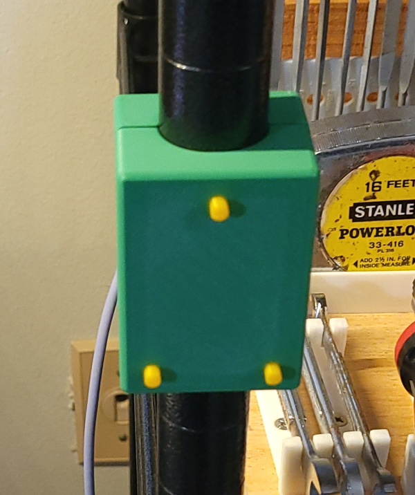
First I need a way to grab the wire shelf post securely. These blocks not only wrap around the post, but also have ridges printed on the inside to match the groves in the post. Four M3x30 bolts screw through the back block into embedded M3 nuts in the front block. The front block has 3D printed holes for 3D printed pins to align with the next disk part.
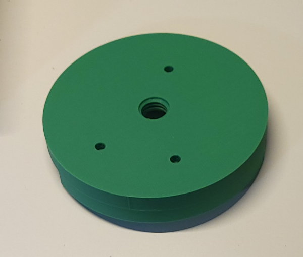
This back disk has M12 threads for a screw hole printed through the center, and matching holes for the pins so it can be aligned with the previous part when glued together.
Some super glue on one half and some kicker sprayed on other half and these parts are securely attached and aligned with the pins.
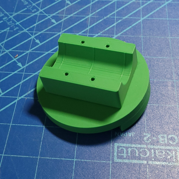
Now it is bolted back on to the wire shelf post.
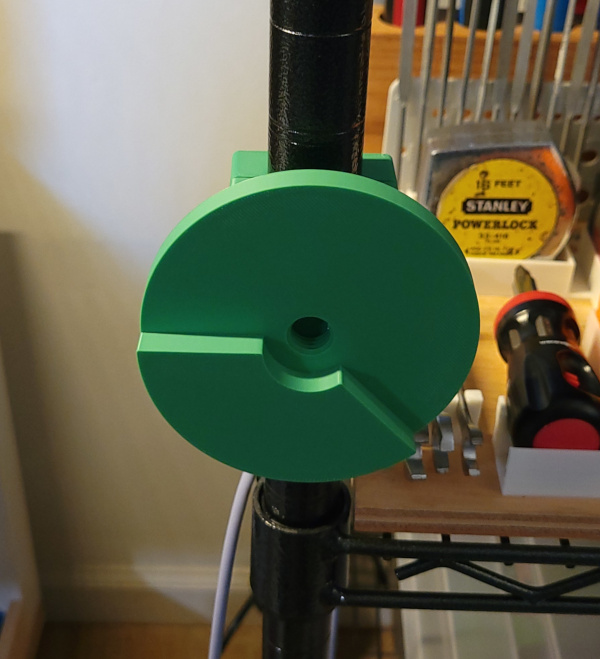
Now need to assemble the front disk where the 3/4 inch loc-line will be attached. The loc-line mount is 3D printed with the shape of a couple of loc-line elements and has screw holes that accept M3x50mm bolts which go through both halves of the mounting block and screw into the M3 nuts embedded in the disk. The mount was large enough that an extra wart needed to be printed on the disk for the embedded nuts. I also run one bolt through the last loc-line element itself for addition security (the mount with two screws in place was a good drilling guide to make the holes in the loc-line).
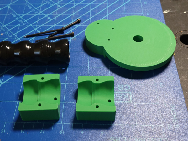
Here is the top disk and mount fully assembled.
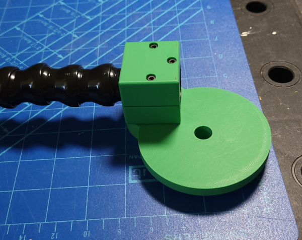
Now everything is mounted to the post. A 3D printed lock screw can secure the two disks together. This is the vertical orientation, getting the loc-line out of the way of the printer.
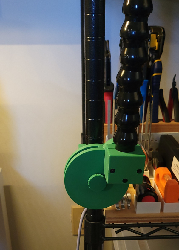
And this is the horizontal orientation, getting the end of the lock-line over in front of the printer.
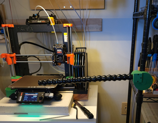
I'll need a case for the Raspberry Pi Zero W and the V2 camera module. I designed one that screws together and uses heatset inserts (because I had some).
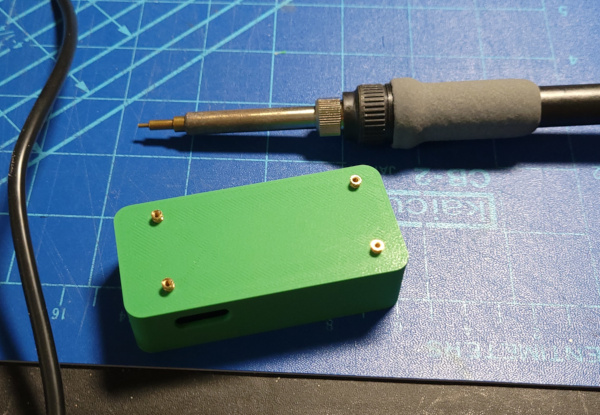
Cranked up the soldering iron and pressed in the inserts.
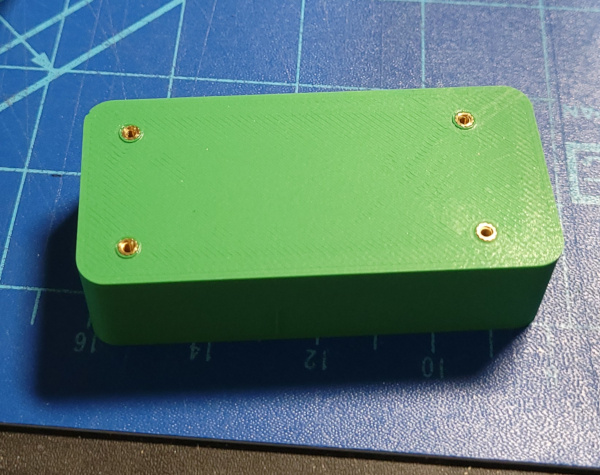
To get the Pi registered correctly in the case, I temporarily screwed in a couple of M2 bolts from the bottom so they stick up a couple of millimeters from the posts. That lets me position the Pi in the case with the holes lined up with the posts.
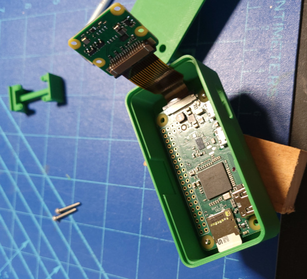
Then I slide in the bracket that holds the camera.
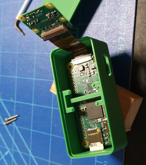
I didn't do this because I didn't think of it in time, but I bet you could insert something like a toothpick through the hole in the top and use it to press the camera down so it sits in the 4 small posts in the camera bracket, then push the top into position while holding down the camera. Once in position, put in the two screws, remove the temporary screws from the bottom and screw them in properly from the top and the webcam is ready for action.
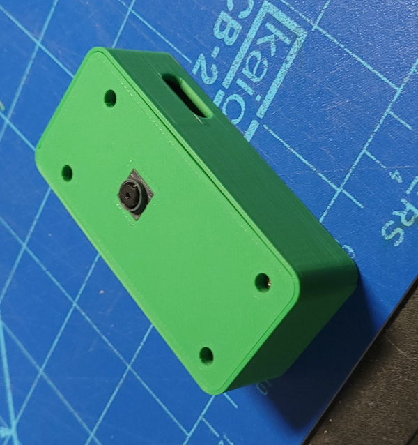
I think I'm going to add some ventilation to this and reprint it, but the procedure for building it will be the same.
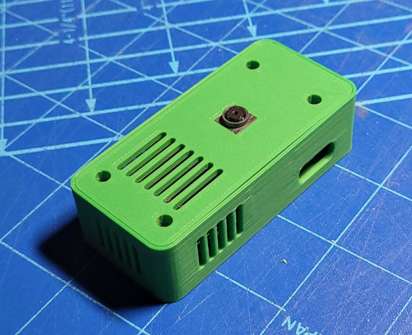
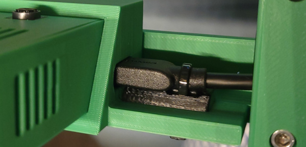
I was surprised the vertical vents printed as well as they did, I also didn't need any supports to print the hole for the power connector.
For the software, I recently tested Spyglass and found it seems to work fine on bookworm (the latest Pi OS release I installed), it is supposed to be able to run as a service, so I should be able to get it to boot directly into webcam mode someday.
I'm printing what I hope are the final parts, but I haven't shown how I embed nuts. I always found it a little tricky because the extruder doesn't like laying down plastic on cold metal, and I finally realized I should print some "toppers" to go over the nuts and make the holes deep enough for the nut plus topper. A thick topper is less likely to pop out of the hole if it gets scraped, so I've been making them 3mm thick. I stick them on bolts above the nuts and wait for the pause I insert on the layer that prints the bridge over the nut holes.
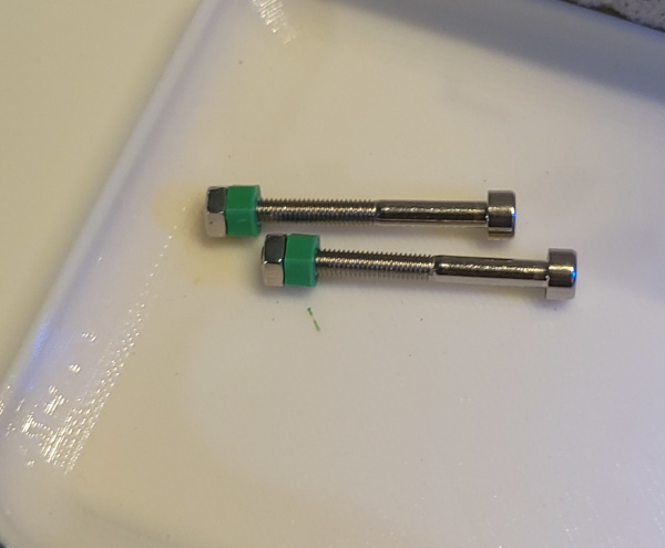
When it pauses, I have nice deep holes.
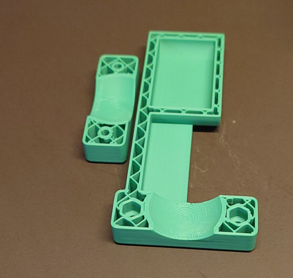
I insert the nut and topper in each hole and hold it down with a fingertip while unscrewing the bolt.
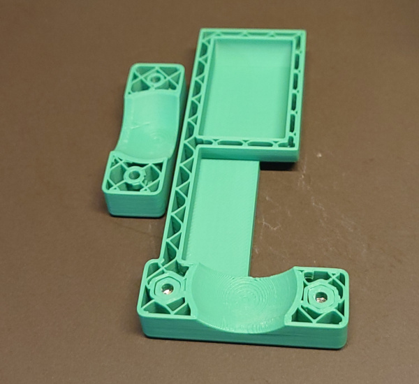
And now I can resume printing and it lays down the bridge over the topper without a problem.
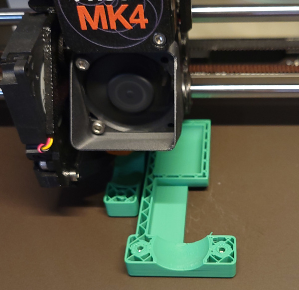
That part has now finished printing.
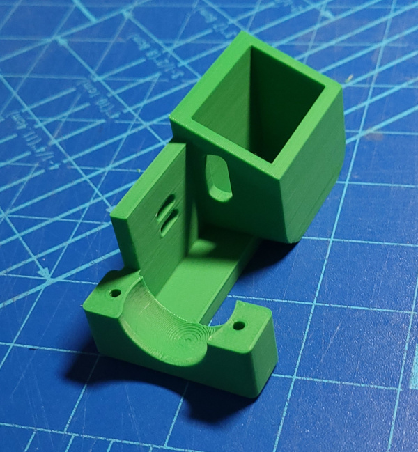
The camera slides in perfectly.
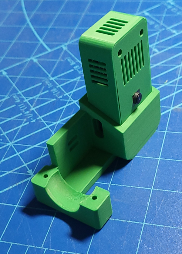
It should clamp solidly to the end of the loc-line.
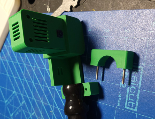
Before clamping down on the loc-line, run the power cable through the loc line and get it plugged in without the end of the loc-line and the top of the clamp in the way. Then clamp on the loc-line after pushing the excess power cable back.
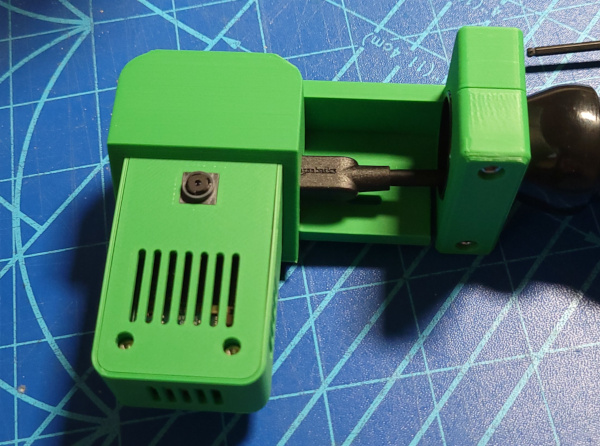
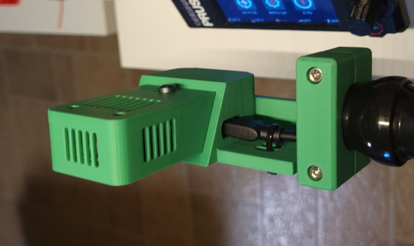
Here it is dangling in front of the printer with a zip tie on the cable (that could be better with some additional support under the cable so I could pull it tight, perhaps I'll add that someday).
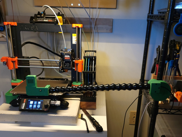
Here's the long view showing the wire shelf post that supports it.
After getting the camera booted, I ran this from the spyglass directory:
python ./run.py -r 1280x720 -f 30
The focus was horrible and the camera was too close to the printer, but I was able to watch the image on my phone while fiddling with the little focus wrench that comes with the camera module and fiddling with the loc-line to reposition the camera.
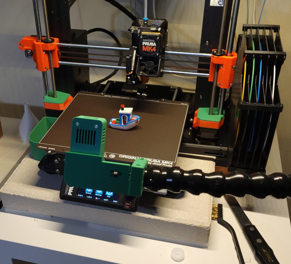
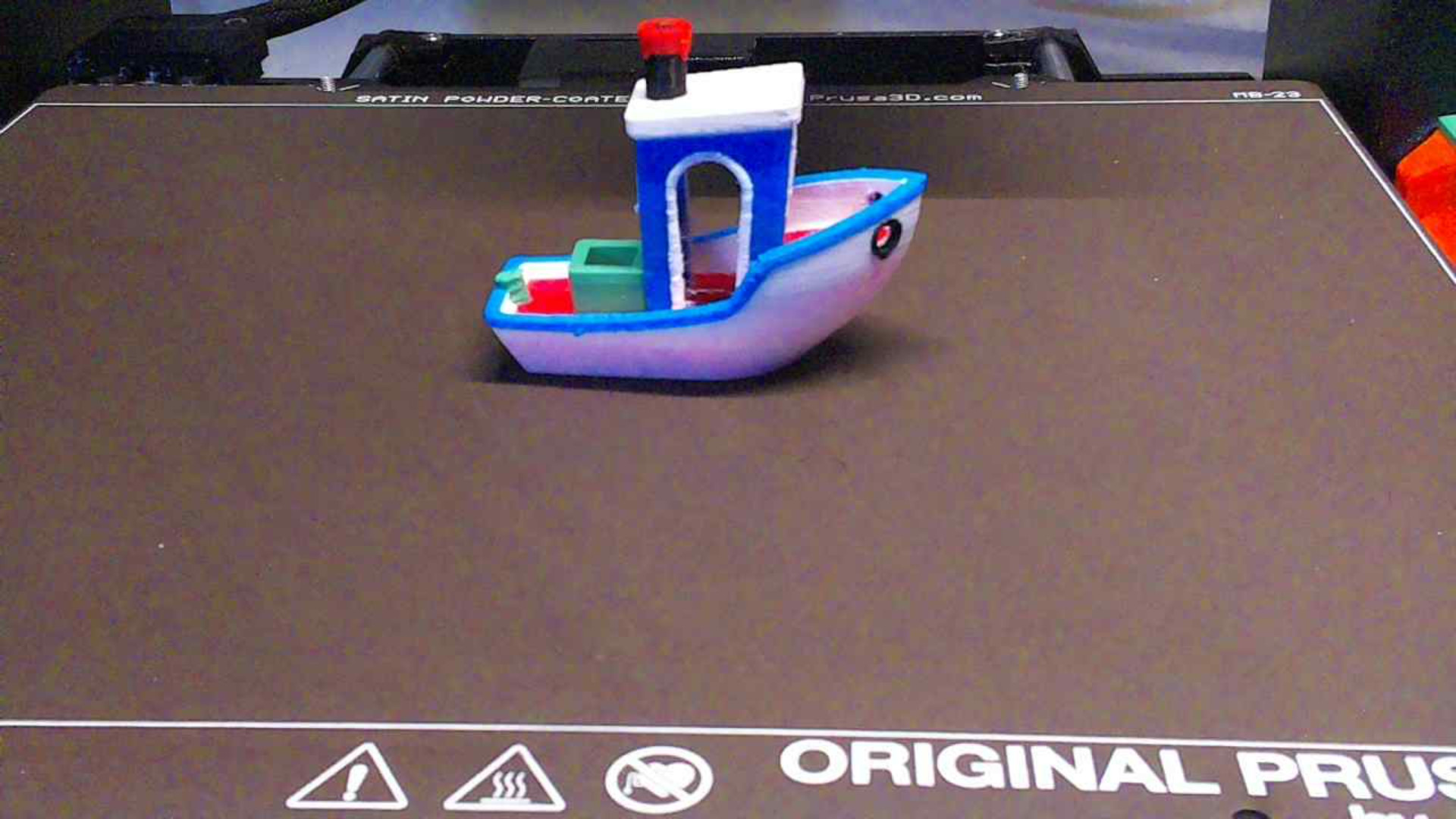
That got me this screenshot of a benchy I printed a while back sitting on the bed.
