Wiring
It is getting close to time to start testing the stop switches and stepper motors and such, so I need to consider how the heck I'm going to run all the cables out of the path of the hardware and down to the smoothieboard.
I have a vague idea that I can put one cable chain on the y carriage running to the bottom rail of the printer and another from the y carriage to the x carriage.
The first step is to print lots of my cable chain pieces so I can test various mounting positions to see if they will work. If I go this way (and I can't think of a better way), I'll probably need to print some new carriage pieces to be able to properly mount the chains.
Certainly I'll want the cables on the opposite side of the printer from the extruder so as not to interfere with the filament.
At the other end of the wires, I'll need to see what needs soldering into the smoothieboard. I have the 5V regulator I know needs to go on. There may be headers I want to add as well. Perhaps I should do the work for adding the heated bed driver while I'm at it even though I don't plan to try heating (or mounting) the bed till much later.
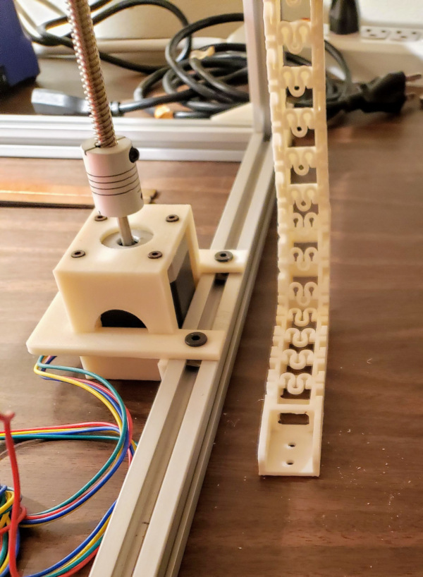
I have printed loads of cable chain (which also involved doing a lot of calibration and adjustment on the solidoodle) as well as the special pieces I need to attach the chains to the carriages.
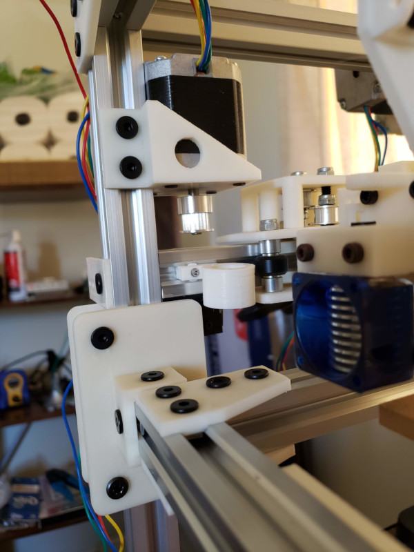
Here's the connection to the X carriage...
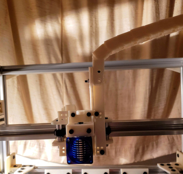
...which runs over to the (right side) Y carriage...
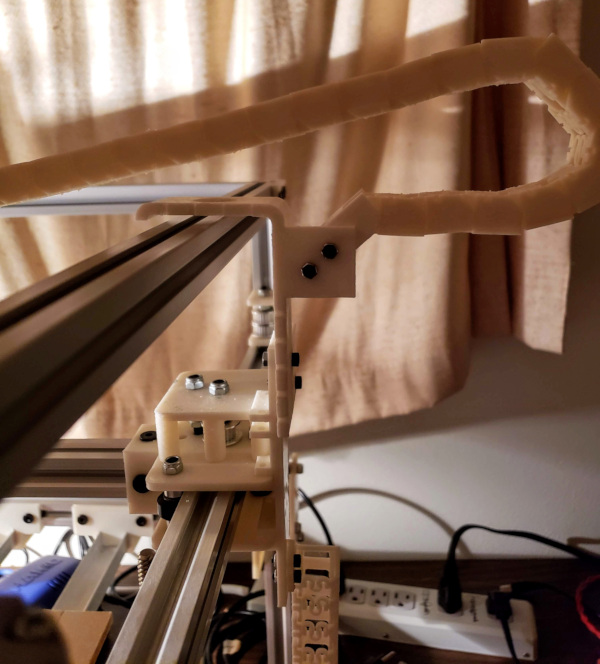
...which drops down to what will be the top of the box holding the electronics.
All this seems to move freely with no resistance through the complete X-Y range (with the bottom of the chain where it will attach to the box motionless).
I need to start thinking about what wires need to run where as well:
To or from the X carriage:
- The hot end heater (two heavy wires).
- The hot end thermistor (two light wires).
- The hot end (always on) cooling fan (two light wires).
- The nozzle PWM controlled cooling fan (four light wires).
- Possibly a PRECISION PIEZO ORION Z-probe (three wires)
To or from the Y carriage:
- Everything from the X carriage goes to Y as well.
- The min and max X stop switches (two wires each, total of 4). One needs to run all the way across the v-slot the X carriage is on, through the top slot and out of the way of the carriage.
To or from the print bed:
- The print bed heater wires (two heavy wires).
- The print bed thermistor (two light wires).
(I don't think I need a chain on the print bed, the wires can just hang free at the back side out of the way of everything else).
Fixed objects on the left side:
- The left side X-Y stepper motor (4 wires).
- The extruder stepper motor (4 wires).
- The min and max Y stop switches (two wires each).
- The left side Z stepper (4 wires).
Fixed objects on the right side:
- The min and max Z-stop switches (two wires each).
- The right side Z stepper (4 wires).
- Possibly a connection for LED light strip (2 wires).
The fixed wires should be able to run along the v-slots and down some conduit into the box.
For wires needing to run inside a v-slot, I now have the wire-slot.scad model to print little pieces that can be dropped into the slot and rotated with a screwdriver to wedge them in place. They have a hole running through them to route the wires and keep them from popping out of the slot.
Stepper (and other) cables that aren't long enough will need to have extensions soldered on. Probably the way to do this is build the extension first so I can get all the connectors crimped correctly and tested, then cut all the wires to the same length and solder them to the ends of the existing stepper wires (I'm less likely to screw up the soldering than I am to screw up the crimping, so do the crimping first). Also, don't forget to put shrink wrap tubing on the wires before soldering or you'll have to pop the individual wires out of the plastic connector to get shrink wrap on.
Aside from the carriage wiring work, I also soldered in all the headers I might need on the smoothieboard. This includes the control signals for the stepper motors in case I ever want to run an external stepper driver for the dual Z-axis motors (for now I just made a short cable to jump two steppers together for driving the Z motors identically).
I also printed a couple of plastic pieces to serve as a mount for the smoothieboard which can be bolted to the box (once I build the box).
Seems like building the box is the next step.
Some information needed for wiring up the box power: The AC receptacle has (left to right with middle pin on the bottom) neutral, ground and line voltage in that order looking into the open end of the receptacle (neutral is white, ground is green, and line is black on the wires currently soldered to the plug). [Actually if you get it under a bright light you can see tiny L N and ground symbols next to those pins on the back of the receptacle].
I think the way to wire up the rocker switch is to have the line voltage come into the switch and out to the line input of the power supply, and the neutral go directly to the power supply neutral input as well as the brass colored tab on the switch to complete the circuit to light up the switch when the power is on. Ground, of course, goes to the ground connection on the power supply (maybe should also go to the frame of the printer). Could still be some question as to which tab on the switch the line input goes to from the wall. [The one farthest away from the brass tab seems to work].
OK. Made up some cables (with middling success using a crimping tool, resorting to solder for ataching some connectors to the wires). Wired everything up as described above, and the switch correctly lights up when I turn it on (with no blown circuit breakers as an added benefit), as well as the light on the power supply turning on as well, so I think I have the AC power part squared away (just need to get the box finished and everything inside it).
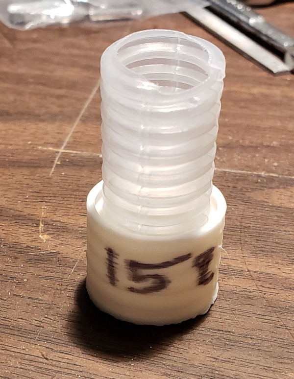
I've been making progress on the box, and need to make sure I can run the wires into the box, so the first thing to do was make a model of the plastic conduit I have and figure out the best way to join it to 3d printed pieces. I used my scanner and gimp to model the edge of a piece of conduit I cut lengthwise, then rotated the .svg file that generated to model the conduit. Scaling that model up by 15% seems to give me an excellent fit when I subtract that shape from the inside of a cylinder, no ordinary force can pull it loose once installed in this test print:
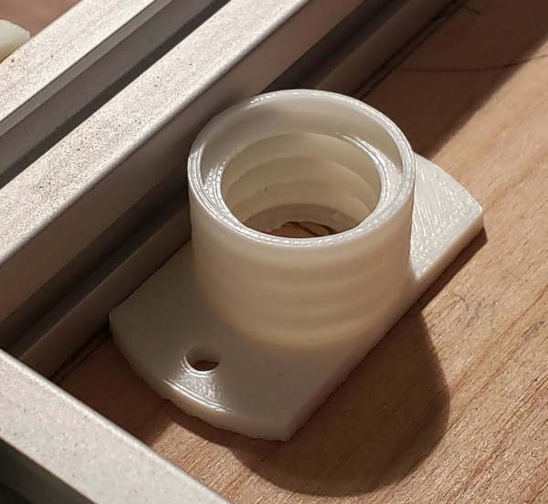
I used that to model a piece I can attach to the box. It will be inside the box sticking up through a hole when fully assembled:
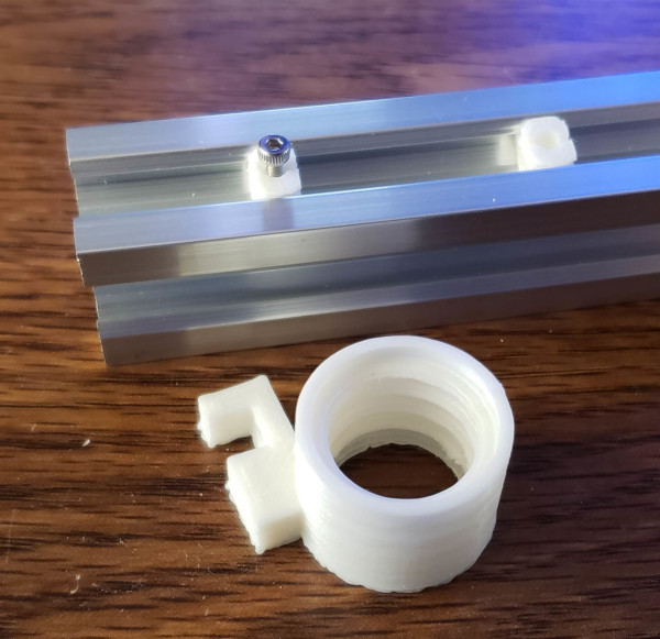
The other end of the conduit will be attached to the v-slot structure of the printer and route the wires from the stepper motors and friends out of the way so they won't get caught on moving parts. Here I have some little v-slot inserts modified to hold an M2 nut and hole for a bolt, and the conduit holder attached to a block that fits over the insert and is bolted down:
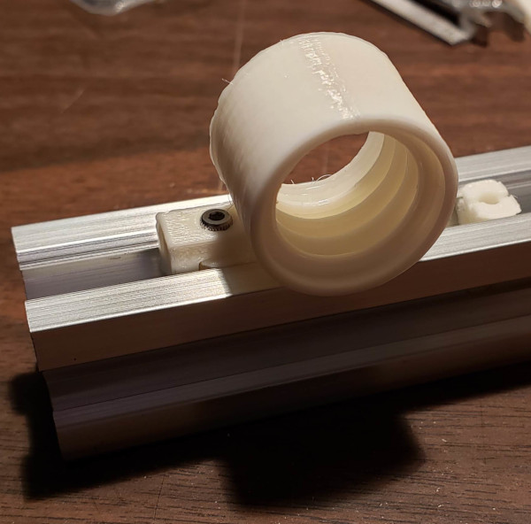
Fortunately it does look like the conduit holder will just fit in a corner where it will clear all of the x, y, and z motion. I'll need to carefully measure exactly where that is and make sure the hole I drill in the box is directly below it.