Rebuild
I've decided that my Z axis with the wheels and v-slots is hopeless. Time to do a complete redesign and rebuild with a mechanism more likely to work right.
I've ordered some 8mm shafts and linear bearings as well as some anti-backlash nuts for the acme screws. I'll need to design and print some parts for holding the bearings on the printbed and holding the shafts for the bearings on the printer frame.
Since my current problem is the printbed rocking instead of staying dead flat, I'll want a couple of linear bearings on each shaft spaced as far apart as will allow the printer to operate to get the greatest possible support against the evil tilting back and forth. (Or at least as far apart as I can print the parts on my old solidoodle with the 6 inch bed). On the other hand, I don't want them so long that the parts themselves flex and introduce twisting that way.
Things to consider:
I'll have to take the printbed completely off. This can be done by unbolting all the plates that hold the wheels at the corners.
This would be a good time to add a connector in the middle of the thermistor cable as well so I can disconnect it without opening up the case.
I'll need to lift the printer off the bottom rails enough to get more t-nuts slid into the slots on the front and back bottom rails for holding whatever mounting I come up with for the shaft ends. This is the trickest part since I'll need to pull some slack in the wires that currently run through the flexible conduits. I'll also need to unbolt the tops of the conduits so they don't stop me from raising the printer frame. Might want to have some small blocks (printed or cut from wood) handy to put under the vertical posts and hold them far enough up to let me get the t-nuts into the rail without completely taking the whole thing apart.
Aside from the conduits, I may also need to unbolt the cable chain from the Y carriage since it probably won't stretch enough. Fortunately all the cable slack already lives right there.
Or instead of trying to wedge blocks in place, maybe improvise some sort of jack mechanism so I can lift the printer frame very gradually without jerking or falling over and stop as soon as I just get room to add the t-nuts. Perhaps salvage parts from the improvised clamp I used on the printbed earlier with 1/4-20 bolts and wingnuts serving as the "jack".
I'll need to add t-nuts to the top rails as well, but that is simpler since they can come off individually (not being bolted to the box like the bottom rails). Maybe add a couple of nuts to the back of the top front rail in case I want to mount a strip of LED lights up there.
The linear bearings are 15mm in diameter and the shafts are 8mm in diameter, so the shaft supports will need to stick out a bit to line up with the linear bearing supports. Possibly, I can compress the printbed a bit so the bearings sit slightly inside the printer frame. I'll see how it goes.
I'll need a different mechanism for hitting the top and bottom Z-stop switches and adjusting the Z level. Possibly just a separate block printed and screwed to the end of the print bed rail that sticks out far enough to hit the switches. Probably will need a different holder for the top switch that faces inward instead of outward.
This will totally defeat the purpose if the bed now moves smoothly, but isn't exactly perpendicular to the x-y motion, so need to make sure I can get things lined up properly. Using the bubble level might be a good place to start. Measuring the separation between the printer and bed at the top and bottom with a micrometer is probably also a good idea.
Useful measurments:
With the bed at Z==0, there are about 150 mm between the top of the rail on the printbed and the top rail on the printer.
With the bed at Z==max, there are about 85mm between the bottom of the rail on the printbed and the bottom rail on the printer.
So the absolute max height of the printbed linear bearing supports would be 85+20+150 (255), which is far too long. The theoretical max I could print on the solidoodle is 150, and practically something smaller than that will be easier to print.
I'll want the piece to wrap around the top and bottom of the printbed rail for stiffness and sink into the v-slot, so the front face will be the bottom when it prints. This means the linear bearing holders will need to be printed separately and probably bolt to the front.
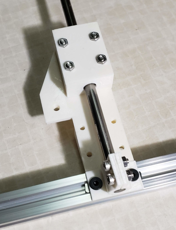
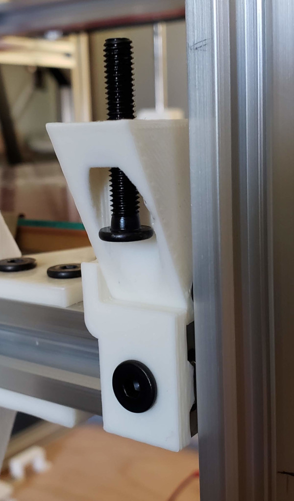
Designed and printed some test pieces for getting bed running on linear shafts. Here's the prototype of the piece that will bolt to the printbed rail and then have linear bearings bolted to it:
The shafts will be anchored at the top and bottom with clamps like so:
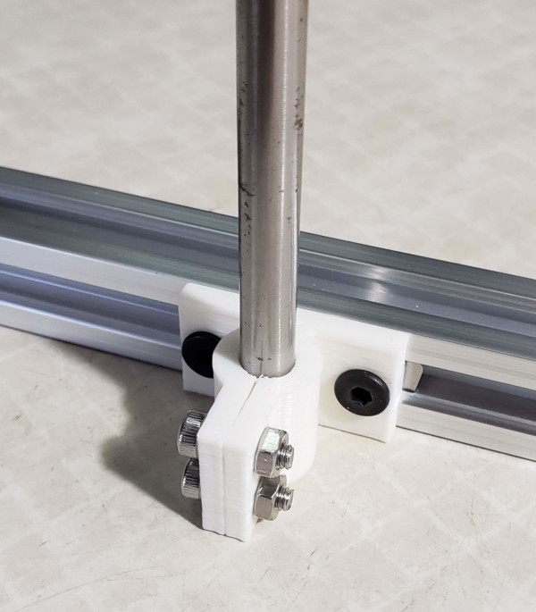
The clamp doesn't seem to need any additional modification. The bracket for the bearings curled up a bit when I printed the prototype, so I've added some holes and grooves for strain relief in the hope it will print better when I print the final versions.
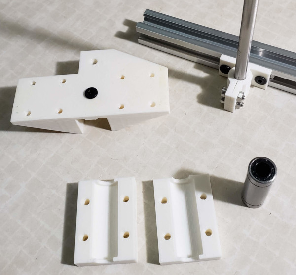
I've now printed a test version of the bearing block, and have a collection of all the parts for testing:
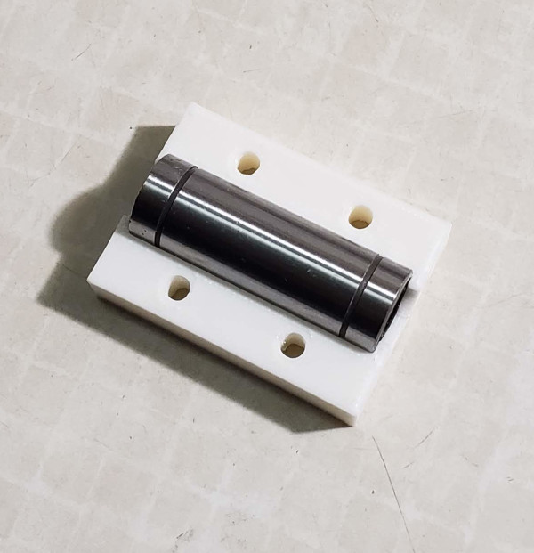
The linear bearing snaps into place very securely (it is quite hard to get out once it is put in):
The top half snaps over the bottom half equally securely, and testing assembly of all the parts shows that it seems to go together quite well:
It takes a while to print the big pieces I'll need to attach the shafts, but while I'm printing, I've been preparing the printer. I added the connector on the printbed thermistor cable. I removed the printbed and all the bits from it associated with the wheels, and now I've hacked up an improvised "jack" to raise the printer off the bottom rails so I can get t-nuts added:
Just need to disconnect everything that won't stretch, and turn the wingnuts to raise the printer very very gradually.
Meanwhile, the 500mm shafts I ordered were delivered, and they certainly appear to be dead straight. I previously ordered more linear bearings than I required, and sorted through them to find a total of 8 which operate smoothly enough to slide down the shafts under their own weight (and don't make any noise), so those are the eight I'll use and the others can be spares or become part of some new feindish device someday.
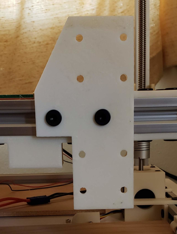
The last few parts are still being printed, but I have the big brackets for the print bed printed and attached (with the new strain relief grooves and holes added), and you can see other parts in the background as well as the shafts and bearings:
Maybe I'll have it put back together tomorrow (depending on how well my jack works and how hard it is to get put back together). The key will be getting it at right angles to X and Y. Maybe get out the printer leveler I hacked up previously and level the X and Y rails then level the print bed the same way before starting to attach the shafts and line up the clamps which grab the shaft ends.
Holy Cow! The jack worked perfectly. Here we have dangling cables and the printer jacked up to clear the slots in the bottom rails:
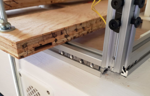
In this close up of one corner, you can see the two additional t-nuts I slid into the rail:
Now just need to lower it back in place and get the corner braces screwed back on to make it all one piece again.
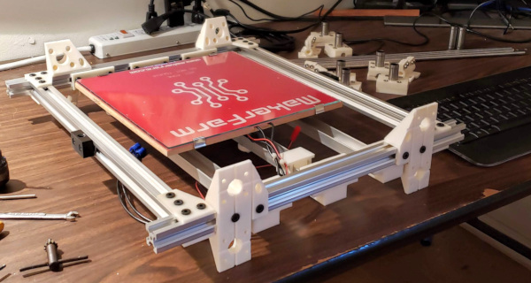
It went back together perfectly, and I got t-nuts installed in the top rails as well. Started putting it together with just a couple of loose screws here and there to see how it all fits:
Finally had a problem: I keep forgetting the top and bottom rails are t-slots, not v-slots, so the shaft clamps don't fit flush with the rails. I better fix the parts and print some new ones before going any farther. Probably won't be back together today.
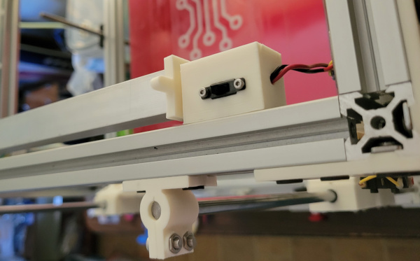
Got the new clamps printed and installed everything. The one new part I still need to design and print is a new z-stop for fine adjustment of the bed level. I got the switch flipped around because I had a mirror version of the switch holder from when I previously had the switch installed on the other side, so I just need the piece to hold an adjustment screw on the printbed.
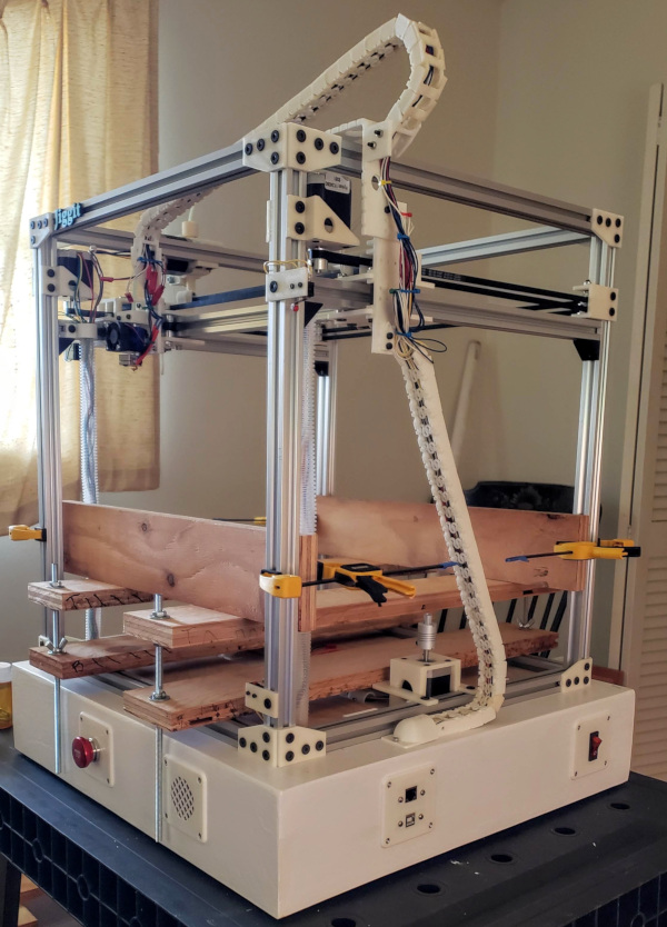
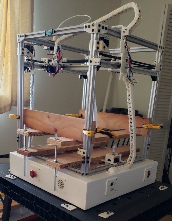
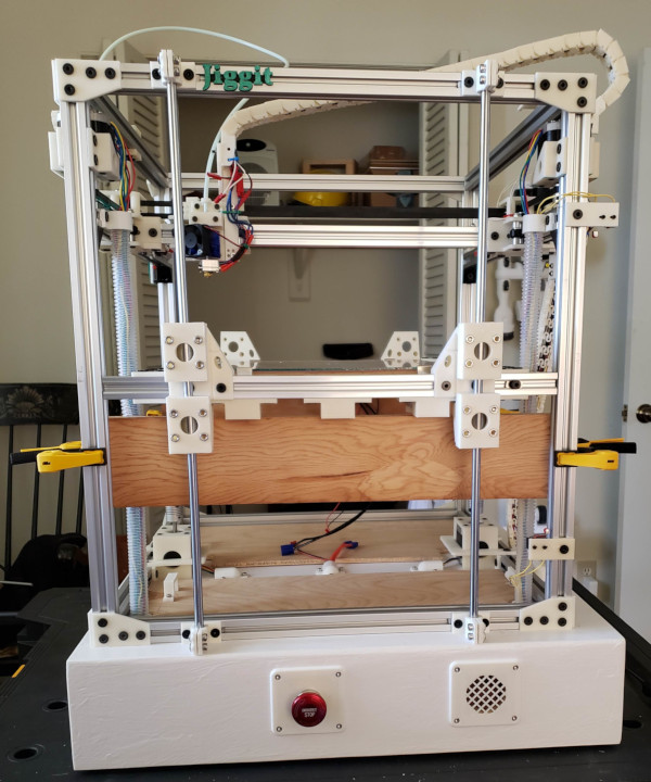
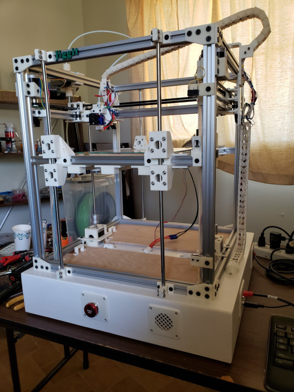
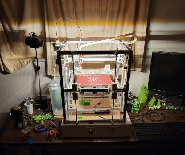
Here's the long shot of the rebuilt Jiggit with the print bed running on 8mm shafts now:
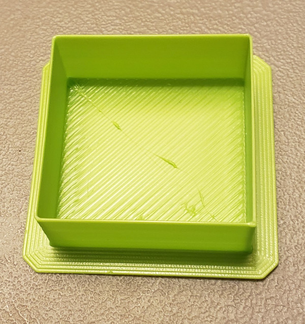
Added adjusting screw, tweaked things as well as I could to be square and properly positioned, and printed a test piece with a single layer bottom to see that the bed level was properly set.
The Z stop level adjustment screw:
The test print showing layer 1 printing (almost) perfectly:
I don't see any rocking or tilting with the new shafts installed. Time to try something complicated.
New tip to remember: A length of scrap filament straightened a bit makes a dandy cable puller to get new wires through the conduit. It even works as a cable pusher, which is what I did to get a red and black pair of wires down the right side conduit to provide power for an LED light strip I'm planning to install.
Speaking of the LED light strip:
I stuck the LED strip to one side of an aluminum angle and built some little parts that grab the angle and can be rotated a few degrees to adjust the light angle. One side connects to a little switch box with a switch so I can turn the light on or off:
Here's what normal lighting looks like a a test I just printed:
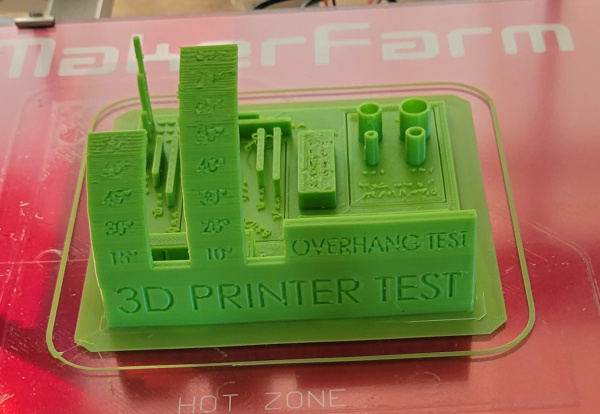
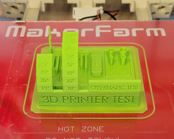
And here's the same test after turning the light on. The flaws are much more vivid:
And here's the room at night with just the LED strip turned on:
Pretty impressively bright.