Printbed
Five years ago (or so) when I started then abandoned this project (for lack of space to work on it), I had gotten the basic print bed structure started with 3 aluminum channels to mount the bed and adjusting screws to. Now that I've retired and cleaned out a room for a 3d workshop, I can try to pick up where I left off.
The first priority is just to get some kind of bed that I can test with. Installing the heated bed is not a priority for now, just something I can put a piece of glass and some blue tape on for PLA printing will do to begin with.
The simplest thing seems to be to get a piece of 1/4 inch MDF from the nearby home depot and cut it to the size of the bed heater so all the geometry will be the same for the day I add the heated bed.
I can put holes for 3 flat head machine bolts, countersunk so the mdf surface is flat. Epoxy the bolts in place and probably epoxy washers on the other side so springs won't dig into the MDF.
The positioning of the bolts only need to be approximate, because I can 3d print some pieces to slide into the aluminum channels with holes the exact size of the bolts. Get everything put together, clamp the printed pieces in place on the channels, then take off the print bed, and use the 3d pieces as a drilling guide to drill through the channels in the exact right location. [This worked great, the holes are drilled and line up perfectly with the holes in the MDF.]
Back to the 3d printer again, and I can print some rings for the top of the springs to keep them centered on the bolt and some squares with spring sized holes to slide into the channels to keep the bottom of the springs centered on the bolts.
Next print some knobs to go on the end of the bolts, and I can adjust the bed level by turning the knobs.
I can clip glass or the heated bed to the top of the MDF with swiss clips or binder clips. Might want to glue some thin metal plates to the bottom of the MDF where the clips slide on to keep it from being torn up by the clips (I've got some aluminum flashing that might be good enough for that, but see below for a possible better idea).
To attach the heated bed, I can probably drill a hole in the MDF for the thermistor wires to go through and grind away some space on the top of the MDF with a Dremel to make room for the bump of the thermistor (but that comes later). The wires can run through the channel till they get near the edge where the Smoothieboard lives, then come out another hole (with a grommet to keep the wires from rubbing on sharp aluminum). Might want a layer of cork in there to insulate the heated bed, but that might get thicker than the clips could handle.
Heated bed note: The thermistor that came with the bed I bought from makerfarm 5 years ago is probably a EPCOS 100k (but I'm not positive of that).
I can imagine things like routing out the top of the MDF, and glueing in some metal mending plates for the clips to go over to get it thin enough again. But again, cross that bridge when I get to it. (Maybe use this Dremel router attachment). Maybe I should do this to start with as the metal would work better with the clips.
Related to the topic of print beds, I've got this renishaw touch probe I built once. If I come up with a way to mount it to the print carriage, I should be able to test the bed level quite easily. If I get really ambitious, I should be able to write a program to tell me exactly how much to turn each adjusting knob to get the bed level.
While waiting for the lead screws, I've been looking at the supports for the printbed traveling up and down the rails, and I'm pretty darn certain the current arrangement is close to hopeless. Facing the printer, the bed shouldn't have a problem rocking right and left because it will be supported by the lead screws on both sides, but rocking 90 degrees from that is a big problem, and the wheels being mounted on the sides don't do much of anything to support it and prevent rocking in that direction. I think I need four wheels on each rail and they need to be on the front and back of the rails, not on the left and right. So I should start designing new carriage pieces and ordering the additional wheels and stuff I'll need.
I currently only have 6 wheels for the print bed carriages, if I want 4 wheels on each rail, I'll need 10 more wheels, and probably ought to get a couple of spares just in case.
On the other hand, I've only got 3 wheels on the x-y carriages and they seem pretty darn solid, so maybe three is all I need on each vertical rail? That would mean I only need 6 more wheels. On the other hand there is a discount rate for buying 10 wheels.
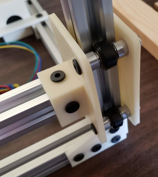
I've redesigned and test printed one (of the 4) z carriage assemblies I'll need, and have discovered that my v-slot doesn't appear to be precisely square (or maybe the slots aren't the same width). My test assembly is slightly loose no matter how far I adjust the eccentric spacer unless I rotate the v-slot 90 degrees. I guess I'll move the center of the eccentric spacer hole in by about 0.4mm (it gives me 1.5mm of total adjustment, so this should be a good number).
OK, another test print (actually no reason not to use these in the final build, they came out perfect), and the slight shift of the eccentric wheel hole works great. I can now get rattle free positioning of the wheels with either side of the v-slot. Infinitely more stable then the nonsense I was trying to do previously.
Here's how it fits on the vertical rail with a scrap of v-slot attached in place of the printbed rail:
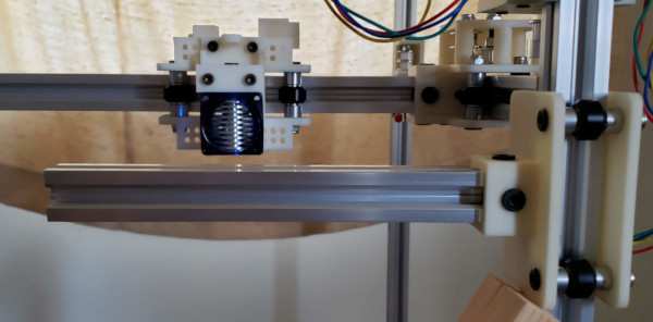
I can move all the way up to just below the E3D before running into something, and I haven't even attached the nozzle or stacked up the printbed material yet, so the top range looks good:
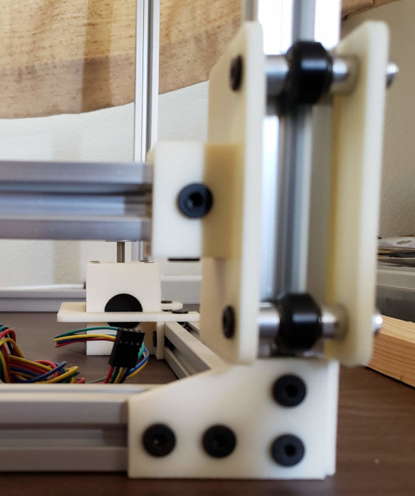
At the bottom range of motion, I dip below the shaft of the Z-axis stepper motors, so that's much lower than I'll ever need to go:
Now I just need 3 more sets of all the parts so I can support all four corners of the print bed this way (got them all printed, should wait till I drill the holes for mounting the actual bed before putting it back together)..
I do need to redesign or at least reposition the z-stop switches. They will need to go on the back or front of the vertical rail and position the switches so the edge of the new z carriage hits the switch. The current z-stop design also includes a small nut trap intended to be glued to the z carriage. That may work perfectly well, though the length of the stops may need to change a bit.
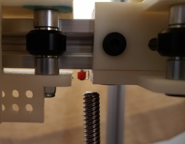
The existing z-stop parts will indeed work correctly if positioned properly:
The little piece with the nut trap can be glued on to provide a fine adjustment screw (it is just sitting on the carriage piece in the picture). I'll probably want to turn the fine adjust bolt upside down and lock a couple of nuts at the other end for the switch to hit. That way I won't have to move the printbed way down to make enough room to turn the bolt.
I suppose if I get really ambitious, I could print a new carriage piece with the nut trap included rather than using glue.
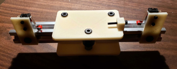
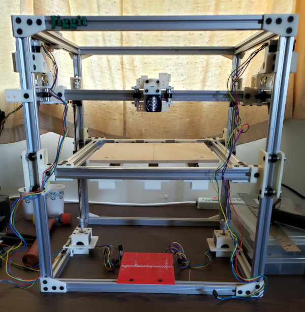
After many weather and Christmas related delays the lead screws I ordered finally arrived, and the good news is that they fit. I have a good 5 or 6 millimeters of clearance between the top of the lead screw and the bottom of the y carriage (I know I tried to calculate things correctly, but it is good to see the calculations confirmed). There won't be any need to cut the stepper motor shafts down:
They also seem to screw into the blocks on the printbed perfectly, so all I need to do is finish putting everything together now that I have all the parts.
Here is how it all goes together:
Now it desperately need to be completely disassembled and put back together with the aid of a machinist square to make all the corners be exactly 90 degrees and everything perfectly square so all the movement will be smooth and nothing will bind up. (After labeling everything properly, of course).
Need to remember to put the new z-stop switches in place during reassembly.
Probably should also include some extra t-nuts in all the slots so I can attach new things without complete disassembly (if I can figure out how to keep them from rattling).