Desk Clock
Just starting on a very very silly project: A 3D printed desk clock that works like Crowley's Devon Tread 1.
My first step was to see if I could make a print in place fully working hinge which could be printed vertically, and by golly my first test actually worked. Here's how the two model pieces fit together for printing:

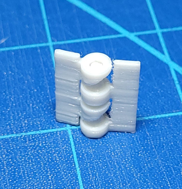
And here's the result:

After breaking free from a bit of stringy stuff, it really can bend like a hinge:

If I can print a single hinge vertically, I ought to be able to print 12 at once joined into a loop of 12 numbers for the hours (likewise with 10 numbers for the two digit minutes). Probably won't try for seconds :-).
For grins I tried printing the test hinge on the solidoodle with PLA instead of the PETG I have on Jiggit. The PLA version worked fine, and has a little more vertical play than the PETG version, so I think the tolerances I have for PETG are just about perfect. The solidoodle may be more accurately calibrated and PLA is definitely less stringy.
Still need to build a final hinge design based on this test, but I've been working on the electronics. I got a Raspberry Pi Zero 2 W. I've soldered the GPIO headers on it. I also bought a kit with stepper motors and drivers.
After a search, I found that probably the latest and greatest approved way to diddle the GPIO pins is via libgpiod and wrote this test program for checking out the individual motors and making sure I could drive them from the Pi:
// Program to test sequencing of coils on stepper motor since some of
// the cheap 28BYJ-48 motors I have seem to be wired wrong. If it is
// just the wrong wire in the socket position, should be able to deduce
// which positions are the right wires by observation (that's the theory).
//
// Turns out the wires aren't wrong at all, what I really discovered using this
// program was that the 800 microsecond delay wasn't good enough for three
// of the five steppers. Bump it up to 900, and they all work.
//
// In any case, this is a fairly useful program for demonstrating how
// to run stepper motors with libgpiod on the raspberry pi.

#include <gpiod.h>
#include <stdio.h>
#include <unistd.h>

// The gpio pins I connect to the driver board
#define BLUE_GPIO 22
#define PINK_GPIO 23
#define YELLOW_GPIO 24
#define ORANGE_GPIO 25

#define GPIO_DELAY 1800

struct gpiod_chip *chip;
struct gpiod_line *lineBlue;
struct gpiod_line *linePink;
struct gpiod_line *lineYellow;
struct gpiod_line *lineOrange;

// Colors of the four wires in the stepper socket
const char * names[4] = {"blue", "pink", "yellow", "orange"};

// All possible orderings of the sequence of 4 pins.
//
int perms[24][4] = {
   {0, 1, 2, 3},
   {0, 1, 3, 2},
   {0, 2, 1, 3},
   {0, 2, 3, 1},
   {0, 3, 2, 1},
   {0, 3, 1, 2},
   {1, 0, 2, 3},
   {1, 0, 3, 2},
   {1, 2, 0, 3},
   {1, 2, 3, 0},
   {1, 3, 2, 0},
   {1, 3, 0, 2},
   {2, 1, 0, 3},
   {2, 1, 3, 0},
   {2, 0, 1, 3},
   {2, 0, 3, 1},
   {2, 3, 0, 1},
   {2, 3, 1, 0},
   {3, 1, 2, 0},
   {3, 1, 0, 2},
   {3, 2, 1, 0},
   {3, 2, 0, 1},
   {3, 0, 2, 1},
   {3, 0, 1, 2}
};

int curperm=-1;

int step_state = 0;
int step_dir = 1;

#define WAVE_STEP 0
#define FULL_STEP 1
#define HALF_STEP 2

int driver=WAVE_STEP;

void
print_curperm() {
   switch(driver) {
   case WAVE_STEP:
      printf("Using wave stepping.\n");
      break;
   case FULL_STEP:
      printf("Using full stepping.\n");
      break;
   case HALF_STEP:
      printf("Using half stepping.\n");
      break;
   }
   printf("permutation[%d]: %s, %s, %s, %s\n",
      curperm,
      names[perms[curperm][0]],
      names[perms[curperm][1]],
      names[perms[curperm][2]],
      names[perms[curperm][3]]);

}

void
reset_step_state() {
   step_state = 0;
   step_dir = 1;
   gpiod_line_set_value(lineBlue, 0);
   gpiod_line_set_value(linePink, 0);
   gpiod_line_set_value(lineYellow, 0);
   gpiod_line_set_value(lineOrange, 0);
}

void
wave_back_forth() {
   int i,j,k;
   struct gpiod_line * lines[4];
   lines[perms[curperm][0]] = lineBlue;
   lines[perms[curperm][1]] = linePink;
   lines[perms[curperm][2]] = lineYellow;
   lines[perms[curperm][3]] = lineOrange;
   for (i = 0; i < 2; ++i) {
      for (j = 0; j < 2048; ++j) {
         switch(step_state) {
         case 0:
            gpiod_line_set_value(lines[0],1);
            gpiod_line_set_value(lines[1],0);
            gpiod_line_set_value(lines[2],0);
            gpiod_line_set_value(lines[3],0);
            break;
         case 1:
            gpiod_line_set_value(lines[0],0);
            gpiod_line_set_value(lines[1],1);
            gpiod_line_set_value(lines[2],0);
            gpiod_line_set_value(lines[3],0);
            break;
         case 2:
            gpiod_line_set_value(lines[0],0);
            gpiod_line_set_value(lines[1],0);
            gpiod_line_set_value(lines[2],1);
            gpiod_line_set_value(lines[3],0);
            break;
         case 3:
            gpiod_line_set_value(lines[0],0);
            gpiod_line_set_value(lines[1],0);
            gpiod_line_set_value(lines[2],0);
            gpiod_line_set_value(lines[3],1);
            break;
         }
         usleep(GPIO_DELAY); // Too small and motor doesn't turn, just vibrate
         step_state += step_dir;
         if (step_state < 0) {
            step_state = 3;
         } else if (step_state > 3) {
            step_state = 0;
         }
      }
      step_dir = - step_dir;
   }
}

void full_back_forth() {
   int i,j,k;
   struct gpiod_line * lines[4];
   lines[perms[curperm][0]] = lineBlue;
   lines[perms[curperm][1]] = linePink;
   lines[perms[curperm][2]] = lineYellow;
   lines[perms[curperm][3]] = lineOrange;
   for (i = 0; i < 2; ++i) {
      for (j = 0; j < 2048; ++j) {
         switch(step_state) {
         case 0:
            gpiod_line_set_value(lines[0],1);
            gpiod_line_set_value(lines[1],1);
            gpiod_line_set_value(lines[2],0);
            gpiod_line_set_value(lines[3],0);
            break;
         case 1:
            gpiod_line_set_value(lines[0],0);
            gpiod_line_set_value(lines[1],1);
            gpiod_line_set_value(lines[2],1);
            gpiod_line_set_value(lines[3],0);
            break;
         case 2:
            gpiod_line_set_value(lines[0],0);
            gpiod_line_set_value(lines[1],0);
            gpiod_line_set_value(lines[2],1);
            gpiod_line_set_value(lines[3],1);
            break;
         case 3:
            gpiod_line_set_value(lines[0],1);
            gpiod_line_set_value(lines[1],0);
            gpiod_line_set_value(lines[2],0);
            gpiod_line_set_value(lines[3],1);
            break;
         }
         usleep(GPIO_DELAY); // Too small and motor doesn't turn, just vibrate
         step_state += step_dir;
         if (step_state < 0) {
            step_state = 3;
         } else if (step_state > 3) {
            step_state = 0;
         }
      }
      step_dir = - step_dir;
   }
}

void half_back_forth() {
   int i,j,k;
   struct gpiod_line * lines[4];
   lines[perms[curperm][0]] = lineBlue;
   lines[perms[curperm][1]] = linePink;
   lines[perms[curperm][2]] = lineYellow;
   lines[perms[curperm][3]] = lineOrange;
   for (i = 0; i < 2; ++i) {
      for (j = 0; j < 4096; ++j) {
         switch(step_state) {
         case 0:
            gpiod_line_set_value(lines[0],1);
            gpiod_line_set_value(lines[1],0);
            gpiod_line_set_value(lines[2],0);
            gpiod_line_set_value(lines[3],0);
            break;
         case 1:
            gpiod_line_set_value(lines[0],1);
            gpiod_line_set_value(lines[1],1);
            gpiod_line_set_value(lines[2],0);
            gpiod_line_set_value(lines[3],0);
            break;
         case 2:
            gpiod_line_set_value(lines[0],0);
            gpiod_line_set_value(lines[1],1);
            gpiod_line_set_value(lines[2],0);
            gpiod_line_set_value(lines[3],0);
            break;
         case 3:
            gpiod_line_set_value(lines[0],0);
            gpiod_line_set_value(lines[1],1);
            gpiod_line_set_value(lines[2],1);
            gpiod_line_set_value(lines[3],0);
            break;
         case 4:
            gpiod_line_set_value(lines[0],0);
            gpiod_line_set_value(lines[1],0);
            gpiod_line_set_value(lines[2],1);
            gpiod_line_set_value(lines[3],0);
            break;
         case 5:
            gpiod_line_set_value(lines[0],0);
            gpiod_line_set_value(lines[1],0);
            gpiod_line_set_value(lines[2],1);
            gpiod_line_set_value(lines[3],1);
            break;
         case 6:
            gpiod_line_set_value(lines[0],0);
            gpiod_line_set_value(lines[1],0);
            gpiod_line_set_value(lines[2],0);
            gpiod_line_set_value(lines[3],1);
            break;
         case 7:
            gpiod_line_set_value(lines[0],1);
            gpiod_line_set_value(lines[1],0);
            gpiod_line_set_value(lines[2],0);
            gpiod_line_set_value(lines[3],1);
            break;
         }
         usleep(GPIO_DELAY/2); // Turn half as much, delay half as much
         step_state += step_dir;
         if (step_state < 0) {
            step_state = 7;
         } else if (step_state > 7) {
            step_state = 0;
         }
      }
      step_dir = - step_dir;
   }
}

int main(int argc, char **argv)
{
   const char *chipname = "gpiochip0";
   char cmd[80];

   // Open GPIO chip
   chip = gpiod_chip_open_by_name(chipname);

   // Open GPIO lines
   lineBlue = gpiod_chip_get_line(chip, BLUE_GPIO);
   linePink = gpiod_chip_get_line(chip, PINK_GPIO);
   lineYellow = gpiod_chip_get_line(chip, YELLOW_GPIO);
   lineOrange = gpiod_chip_get_line(chip, ORANGE_GPIO);

   // Open lines for output
   gpiod_line_request_output(lineBlue, "stepcheck", 0);
   gpiod_line_request_output(linePink, "stepcheck", 0);
   gpiod_line_request_output(lineYellow, "stepcheck", 0);
   gpiod_line_request_output(lineOrange, "stepcheck", 0);

   for ( ; ; ) {
      fputs("cmd> ",stdout);
      fflush(stdout);
      fgets(cmd,sizeof(cmd),stdin);
      if (cmd[0]=='p' || cmd[0] == 'P') {
         ++curperm;
         if (curperm >= 24) {
            curperm=0;
         }
         print_curperm();
         reset_step_state();
         switch(driver) {
         case WAVE_STEP:
            wave_back_forth();
            break;
         case FULL_STEP:
            full_back_forth();
            break;
         case HALF_STEP:
            half_back_forth();
            break;
         }
      } else if (cmd[0]=='w' || cmd[0]=='W') {
         driver=WAVE_STEP;
         printf("Use wave stepping to drive motor\n");
      } else if (cmd[0]=='f' || cmd[0]=='F') {
         driver=FULL_STEP;
         printf("Use full stepping to drive motor\n");
      } else if (cmd[0]=='h' || cmd[0]=='H') {
         driver=HALF_STEP;
         printf("Use half stepping to drive motor\n");
      } else if (cmd[0]=='z' || cmd[0]=='Z') {
         printf("Reset current permutation\n");
         curperm=-1;
         reset_step_state();
      } else if (cmd[0]=='q' || cmd[0]=='Q') {
         printf("Bye!\n");
         break;
      } else {
         printf("q - quit\n\
p - try next permutation of wires\n\
z - reset to initial permutation\n\
w - use wave stepping\n\
f - use full stepping\n\
h - use half stepping\n\
otherwise print this help.\n");
      }
   }
   gpiod_line_release(lineBlue);
   gpiod_line_release(linePink);
   gpiod_line_release(lineYellow);
   gpiod_line_release(lineOrange);
   gpiod_chip_close(chip);
   return 0;
}
A vast amount of helpful information came from this video, and this web page.
No doubt the Raspberry Pi is overkill, but it does have WiFi, so I should be able to get the time off the internet to keep the clock accurate :-).
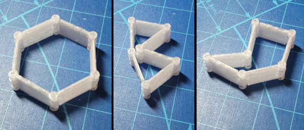
Back to 3D printing, I now have one chain printed in place with six panels for digits 0 through 5:

After breaking any initial threads inside the hinges, they all turn perfectly freely with no resistance.
I guess I need to think about gears to turn the chain now (an equilateral triangle shape is probably simplest). I already bought some small stainless steel rods to use as axles, so it should be simple to try out.
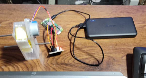
Here's my test rig with the 28BYJ-48 stepper mounted at the top, enough space so the chain can be rotated freely and the bottom axle in a slot so it can move up and down (only cylinders have centers that stay the same distance apart as they rotate :-).

And here it is in operation running the very first test:
Vast amounts of work to do yet, but it is taking shape. I'll want the axles cut to a reasonable length and the bottom axle spring loaded in the final version and nice 3D printed digits on the chain, not to mention an enclosure for everything, but nothing looks impossible yet.
I've been working on a new program to see if I can reliably rotate from one digit to the next over and over again without gradually drifting out of position without any kind of feedback (because everything will be much simpler if I don't need to rig up some kind of switch on one number in each chain).
To do this I need to know the precise gear ratio the motor uses, and I found a lot of different opinions about that on the internet. Apparently different manufacturers use different gears so some experimentation was required. Turns out that my motors are exactly 64:1, at least I don't get any drift after running a long time using that ratio.
Here's my new test program:
// Program to test clock functioning. The clock uses 28BYJ-48 stepper motors
// to turn an equilateral triangle "gear" and bring a new digit on a
// 3D printed "chain" up by turning 120 degrees.
// Try to guess if I'm compiling this on the Raspberry Pi if I haven't
// already been told.
#ifndef COMPILING_ON_PI
#ifdef __arm__
#define COMPILING_ON_PI 1
#else
#define COMPILING_ON_PI 0
#endif
#endif
#if COMPILING_ON_PI==1
#include <gpiod.h>
#else
// Dummy up the defs I use just so I can test compile the code on x86 to
// check for syntax errors
struct gpiod_chip {
int dummy;
};
struct gpiod_line {
int dummy;
};
extern int gpiod_line_set_value(struct gpiod_line*,int);
extern struct gpiod_chip* gpiod_chip_open_by_name(const char *);
extern struct gpiod_line* gpiod_chip_get_line(struct gpiod_chip*,int);
extern int gpiod_line_request_output(struct gpiod_line*,const char *,int);
extern int gpiod_line_release(struct gpiod_line*);
extern int gpiod_chip_close(struct gpiod_chip*);
#endif
#include <stdio.h>
#include <unistd.h>
#include <fcntl.h>
#include <sys/select.h>
#include <math.h>
// The gear train in the 28BYJ-48 has gear ratios of 32/9, 22/11, 26/9, 31/10
// and the motor shaft turns 11.25 degrees on one step (I'm not using
// half stepping). So the angle a single step turns is:
// I don't think this is right. I drift really quickly away from the expected
// angle using these numbers.
//#define ONE_STEP_ANGLE (11.25/(((double)(32*22*26*31))/((double)(9*11*9*10))))
// I also drift using this number
//#define ONE_STEP_ANGLE (11.25/63.65)
// Lets try the claimed 64:1. Dang! This works much better than the others
// Possibly even perfectly
#define ONE_STEP_ANGLE (11.25/64.0)
// I found a web page that claims different manufacturers use slightly different
// gear ratios, and I guess that's true because the motors I have act as if
// they are exactly 64:1
// The gpio pins I connect to the driver board
#define BLUE_GPIO 22
#define PINK_GPIO 23
#define YELLOW_GPIO 24
#define ORANGE_GPIO 25
#define GPIO_DELAY 1800
struct gpiod_chip *chip;
struct gpiod_line *lineBlue;
struct gpiod_line *linePink;
struct gpiod_line *lineYellow;
struct gpiod_line *lineOrange;
// Colors of the four wires in the stepper socket
const char * names[4] = {"blue", "pink", "yellow", "orange"};
int step_state = 0;
int step_dir = 1;
int prompt_visible = 0;
// Wait for a commnd on stdin for up to "msec" microseconds. If msec
// is 0, wait forever. Return 1 if input is available, 0 if
// timed out.
//
int
cmd_available(long msec) {
struct timeval tmout;
struct timeval * tmoutp;
int fd, rval;
fd_set infds;
if (msec == 0) {
tmoutp = (struct timeval *)0;
} else {
tmout.tv_usec = msec % 1000000;
tmout.tv_sec = msec / 1000000;
tmoutp = &tmout;
}
fd = fileno(stdin);
FD_ZERO(&infds);
FD_SET(fd, &infds);
if (! prompt_visible) {
printf("cmd> ");
fflush(stdout);
prompt_visible=1;
}
rval = select(fd+1, &infds, NULL, NULL, tmoutp);
return (rval == 1);
}
void
read_command(char * buf, int buflen) {
prompt_visible=0;
size_t saw = read(fileno(stdin),buf,buflen-1);
if (saw <= 0) {
buf[0] = 'q';
buf[1] = '\0';
} else {
if (buf[saw-1] == '\n') {
--saw;
}
buf[saw] = '\0';
}
}
void
reset_step_state() {
step_state = 0;
step_dir = 1;
gpiod_line_set_value(lineBlue, 0);
gpiod_line_set_value(linePink, 0);
gpiod_line_set_value(lineYellow, 0);
gpiod_line_set_value(lineOrange, 0);
}
// Turn the stepper motor as close as possible to the given angle. Remember
// any fraction it was unable to turn so it can be added in on the next call.
// If angle is positive, turn clockwise, if negative, turn counterclockwise.
//
// NOTE: Using some rational arithmetic package would allow perfection,
// but I'll see how it goes with just double floats doing the work.
//
void turn_through_angle(double deg) {
static double last_fraction = 0.0;
int next_dir;
double dsteps, last_int;
long int step_count, i;
if (deg < 0) {
deg = -deg;
next_dir = -1;
} else if (deg > 0) {
next_dir = 1;
} else {
return;
}
dsteps = deg/ONE_STEP_ANGLE;
if (next_dir == step_dir) {
dsteps += last_fraction;
} else {
dsteps -= last_fraction;
}
last_fraction = modf(dsteps, &last_int);
step_count = (long int)last_int;
fflush(stdout);
step_dir = next_dir;
for (i = 0; i < step_count; ++i) {
step_state += step_dir;
if (step_state < 0) {
step_state = 3;
} else if (step_state > 3) {
step_state = 0;
}
switch(step_state) {
case 0:
gpiod_line_set_value(lineBlue,1);
gpiod_line_set_value(linePink,1);
gpiod_line_set_value(lineYellow,0);
gpiod_line_set_value(lineOrange,0);
break;
case 1:
gpiod_line_set_value(lineBlue,0);
gpiod_line_set_value(linePink,1);
gpiod_line_set_value(lineYellow,1);
gpiod_line_set_value(lineOrange,0);
break;
case 2:
gpiod_line_set_value(lineBlue,0);
gpiod_line_set_value(linePink,0);
gpiod_line_set_value(lineYellow,1);
gpiod_line_set_value(lineOrange,1);
break;
case 3:
gpiod_line_set_value(lineBlue,1);
gpiod_line_set_value(linePink,0);
gpiod_line_set_value(lineYellow,0);
gpiod_line_set_value(lineOrange,1);
break;
}
usleep(GPIO_DELAY);
}
}
// Turn each digit into place, pause 1/4 second, turn again (till
// a new command shows up).
//
void run_clock() {
for ( ; ; ) {
turn_through_angle(120.0);
if (cmd_available(250000)) {
break;
}
}
}
int main(int argc, char **argv)
{
const char *chipname = "gpiochip0";
char cmd[80];
double deg;
// Open GPIO chip
chip = gpiod_chip_open_by_name(chipname);
// Open GPIO lines
lineBlue = gpiod_chip_get_line(chip, BLUE_GPIO);
linePink = gpiod_chip_get_line(chip, PINK_GPIO);
lineYellow = gpiod_chip_get_line(chip, YELLOW_GPIO);
lineOrange = gpiod_chip_get_line(chip, ORANGE_GPIO);
// Open lines for output
gpiod_line_request_output(lineBlue, "stepcheck", 0);
gpiod_line_request_output(linePink, "stepcheck", 0);
gpiod_line_request_output(lineYellow, "stepcheck", 0);
gpiod_line_request_output(lineOrange, "stepcheck", 0);
for ( ; ; ) {
cmd_available(0);
read_command(cmd,sizeof(cmd));
if (cmd[0]=='r' || cmd[0] == 'R') {
reset_step_state();
run_clock();
} else if (cmd[0]=='q' || cmd[0]=='Q') {
printf("Bye!\n");
break;
} else if (sscanf(cmd,"%Lf",°,NULL) == 1) {
printf("Turning %Lf degrees.\n",deg);
fflush(stdout);
turn_through_angle(deg);
} else {
printf("q - quit\n\
r - run clock till new command enered.\n\
degrees - turn stepper this many degrees (if negative turn in reverse)\n\
otherwise print this help.\n");
}
}
gpiod_line_release(lineBlue);
gpiod_line_release(linePink);
gpiod_line_release(lineYellow);
gpiod_line_release(lineOrange);
gpiod_chip_close(chip);
return 0;
}
This will probablly evolve into the code I use to set the clock to a specific time, then start a service that will run the clock once the actual wall time reaches that setting. It currently turns the gear every 1/4 second rather than every 10 minutes. It gets the motor slightly warm doing that, but in the actual clock, the most frequent turn rate will be once a minute, so I wouldn't expect any heat build up from that.
The tricky bit is that the 120 degrees it needs to turn isn't an exact multiple of steps, so it keeps track of the fraction it didn't turn and adds it in to the next turn so on average it stays accurate without drifting out of position.
...
I took a rest from working on this to do other stuff, but now I'm back and got a slider built to test the axle going up and down. I first tried springs to keep tension on it, but couldn't get that to work. The motor wasn't powerful enough to compress the spring. So I switched to gravity instead. Here I've added a little paper bin I (eventually) dumped 62 grams worth of nuts and washers into and the motor kept going with that load, and that weight was also adequate to keep tension on the system:
So the next step is coming up with a better slider to hang weights from.