Solidoodle Titan Aero
This is the extended saga. A shorter summary of what worked can be found here.
I've published the parts as Solidoodle Titan Aero conversion on thingiverse.
After printing most of the parts for Jiggit on the old solidoodle, I've now removed the X carriage on the solidoodle:
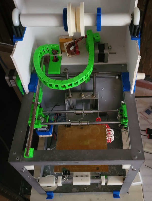
I'm working on printing new parts on Jiggit to mount the Titan Aero extruder/hot end combo on the solidoodle (to turn the solidoodle into a lean mean flexible filament printing machine).
This is a challenge because the tip of the nozzle on the Aero is only about 22mm below the base, so the X carriage needs to be thin enough that the nozzle can reach the print bed. (The linear bearings the carriage sits on are 15mm in diameter, so there isn't much margin.)
Since I have to replace the whole X carriage, I'm looking at correcting old things that annoyed me about the old carriage. For one thing, I'm not willing to put up with anything that needs nuts on the underside where they can fall off when you are trying to adjust something.
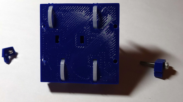
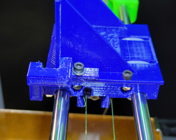
I converted the solidoodle to use fishing line rather than belts a long time ago, so I can make the new carriage exculsively for fishing line. Replacing or installing the line was always incredibly finicky, so I'm trying to fix that with some new parts:
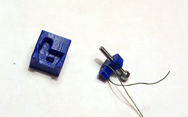
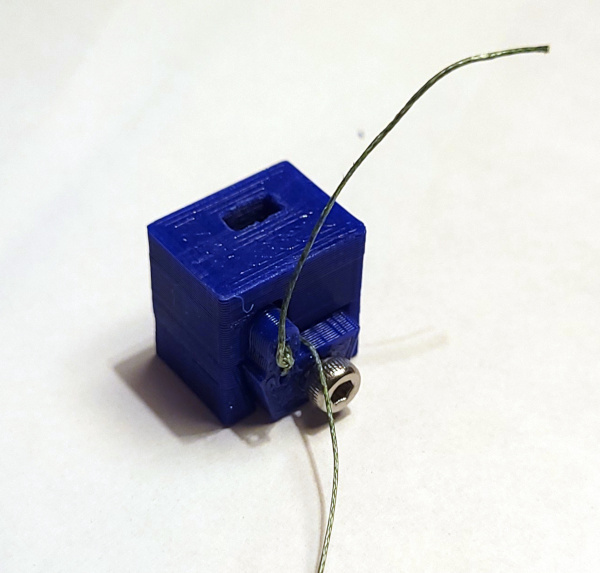
The cube is just a test print with the relevant carriage bits subtracted out so I can test how the other part fits. It is designed to hold the fishing line a couple of different ways, but an important point is the irregular shape so it can't rotate once engaged with the carriage (tired of line wrapping around my hex driver). The matching shape in the carriage will be positioned so the fishing line positioned at the corner shown will line up with the edge of the pulley so all the force will be applied in a straight line.
The line on the side of the carriage which will have the screw for adjusting the tension comes in at the corner, then back around through the holes and is tied so the line will move when the screw is turned. You can see (if you can make it out) the adjuster block can be screwed into the carriage:

That slot on the top of the carriage piece is where a nut is dropped in for the screw to engage with.
The same adjuster block is used to anchor the line on the other side of the carriage, but in this case, rather than being tied, it just comes through the bottom hole where you can pull it taunt while screwing it all the way down at which point the line is clamped and will not move.
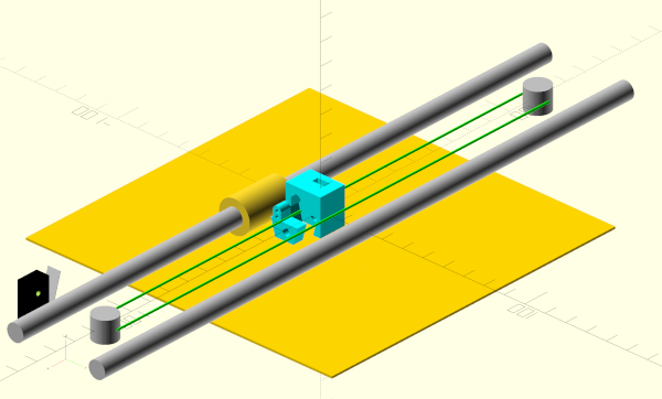
Those photos aren't very good, here's a visualization that might show how these will fit on the solidoodle better:
I'm imagining the procedure is:
- Tie the line to a block and screw that block into the left side of the carriage deep enough to get the screw head out of the way of anything else on the left side of the printer.
- Now take the line coming out of the block and wrap it three times around the drive pulley (tweezers will be handy here).
- Run the line under the carriage around the pulley on the right side.
- Run the line around the corner of the block and back through the bottom hole.
- Insert the block in the carriage and screw it down tight while keeping the line coming out of the hole taut.
- Go back to the left side and adjust the tension as desired.
I'd rather forget what I had to go through before (it often involved blobs of play doh being used to try to keep nuts from falling out), hopefully this will work much better.
Gazillions of things left to design, but these part tests seem to work well (after a few false starts designing parts with tiny impossible to print details).
Very much a work in progress. Other things to deal with:
- Need to finish design of the carriage itself. This will mostly involve figuring out the best way to secure it to the linear bearings without having to take everything apart. (Wire ties might be quick and easy if I incorporate slots for them in the design - I found something called "low profile" ties that might work better and ordered some to check out.)
- I'll need a new "tower" to connect the new carriage to the cable chain.
- I'll need a new part cooler arrangement (I've ordered some raidial fans I might be able to wedge in somewhere easier than a normal fan).
- I'll need to make sure to put something for mounting an adjustment screw for hitting the X stop switch to detect home position.
- Make sure to put some handy spots for wire ties on the new carriage to keep the cables neat.
- I'll definitely need a new mount for the Z stop screw with the bed now having a radically different zero position.
- Perhaps scatter around a few holes and nut traps for any future additions?
- Maybe I can incorporate a dial gauge mount to simplify bed leveling?
I'll probably think of more before I'm through.
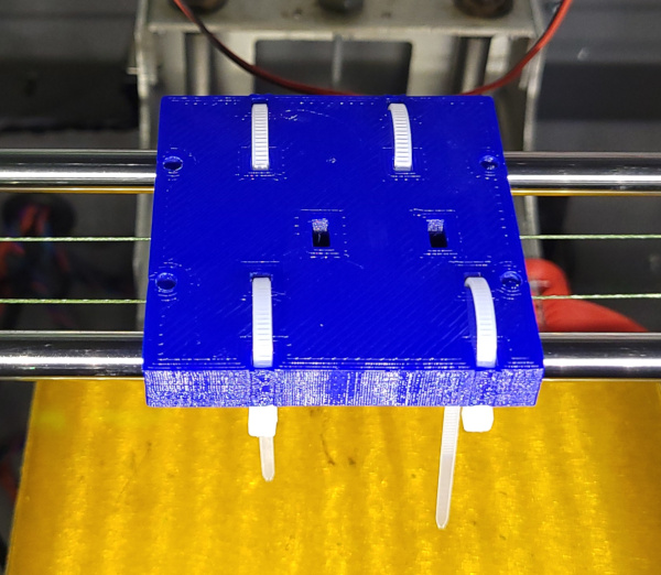
Continuing to design and prototype parts, I've now printed the first test of the whole carriage:
Mounting it was a little easier, but still a pain fooling with the little blocks and trying to keep the fishing line from wrapping around something in the wrong direction, but it did essentially work as planned above. In particular, being able to pull the line taut on the anchor side before screwing the block all the way down was a huge help in getting proper tension on the line. I called the old carriage incredibly finicky, I'd say this is moderately finicky :-).

Harder to photograph from below, but you can see the line running through the open space in the back of the carriage.
But wait! If I lower the bed a lot and use selfie mode, I can get a better shot:

I wanted to test this, but the firmware complained about the hot end temp out of range (duh - it wasn't connected), so I plugged the thermistor cable back in, and then was able to move the carriage back and forth with the Repetier Host manual controls (being careful not to ram it into the ends). Seemed to work fine after placating the firmware.
This is still just a test. This carriage has no holes for mounting anything and isn't positively secured to the linear bearings (though it push fits pretty well), but so far the design is looking good.
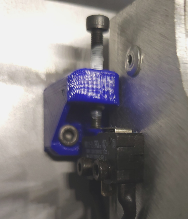
While waiting for the aero to arrive, I figured I'd try making a new Z stop and checking out how far I can raise the bed. This is the old (much too low) Z stop:

Just as well that I checked because there are a few problems. The first is that the Y Rod Bearing I added a long time ago collides with the top of the carriage when I raise it enough. Unscrewed it, and busted the printed parts to get them off. The bearing can hang around spinning freely on the rod till I have some other reason to remove it. The second problem is that the M3 rod I used in the Z-Axis Replacement is too short and doesn't stay all the way inside the M3 threads on top of the carriage. Fortunately Broward Bolt stocked stainless M3 rods and a quick trip got me a new rod I can cut down to size. The third problem is that the Stabilizer I added runs into bolts on the side of the solidoodle frame when I try to move that far up. I guess it has to go.
I've now removed the Y Rod Bearing and the Stabilizer, and cut a new piece of M3 rod about 3/4 inch longer than the old one. I was able to replace the rod without having to take everything apart, and with a little lithium grease everything is running smoothly in the Z direction again. I printed a new Z stop and tested that it fit OK:
With the bed now able to get close enough to make me wince, I see I've got a little less than 18mm from top of carriage to the bed (and I wouldn't want to try moving it any closer than that). Since I needed 22 or less, I've actually got 4mm to spare :-).
I've removed the new Z stop now and epoxied the nut into the trap and when it is dry enough, I can mount it on the printer again and try some teflon tape on the adjusting screw to see if that will make it tight enough (otherwise I guess I'll need some locktite).
Meanwhile, with excellent timing, the Titan Aero kit arrived in the mail, so I can be looking at putting it together and finding out exactly how I want it to fit for the final design of the new carriage.
The Aero assembly instructions involve mounting the motor one one side of a bracket and the extruder on the other, so I'll need to get my existing motor out of the mess of cables as one step in the assembly. Probably just remove all the clips from the cable chain and get all the cables out since there will be other things I need to do like solder or crimp new connectors on some of them.
I guess I need to print the standard bracket as something to use in the initial assembly even though I may redesign it later. That will use up 2mm of my spare 4mm of vertical space :-).
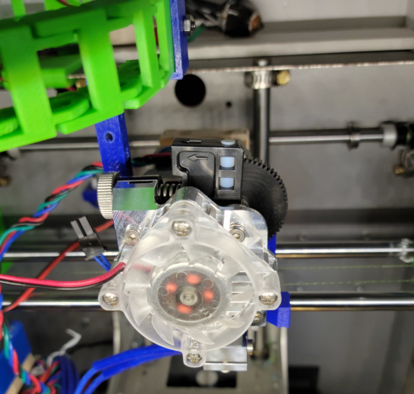
Well, I printed a bracket, and assembled the aero. All went as the instructions called for except one tiny glitch: The "shake proof washer" is too thick for me to engage the screw threads on the bolt through the bearing. I finally gave up and just finger tightened it without the washer. Perhaps on the final bracket I'll print it laying on the face to make sure it is completely smooth and no irregularities are in the way. I could also make it an exact multiple of layer height (which would be 1.85mm rather than 2mm) so the slicer doesn't decide to make it too thick.
Just sitting it on the carriage to see how it fits, here's the front:
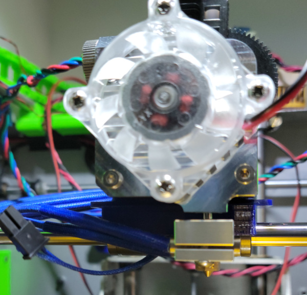
...and the top:
One thing that is immediately obvious when I move it around: The fan sticks out front far enough to run into the top of the solidoodle frame if I try to print all the way to the front of the bed, so I'll lose a few millimeters of bed depth. If I shove it as close to the carriage as I can get, the heat block jams against the edge of the carriage, which would not be a good thing to do. I will probably do some combination of losing a little more bed by moving it out from the carriage, and carving out a recess in the carriage just behind the heat block.
I'll also lose a few millimeters on the left side of the bed because everything is just too big to move far enough left for the nozzle to reach the edge (and the nozzle is also offset towards the right side of the assembly). Losing space like this probably isn't a big deal since other than the TARDIS I printed, I've never used the whole bed.
The cable chain was previously attached over on the right side of the extruder assembly, and I think I need to do the same on the new bracket otherwise the path for the chain will be too compressed. This means I need to run the heater and extruder out the other side of the heater block. Also, I noticed that the extruder stepper was the one I had to extend the cable on to run through the chain. It may need more extension and in any case the previous job was kind of crappy. I can do better now, so I should probably fix that while I have it out of the printer.
I don't have any places I could screw down the bracket near the front, but if I'm going to make the carriage wider, I could probably include some nut traps located outside the bearings where I'd have more room. In the back there is plenty of room for nuts in the channel the back line slides through. I could also extend the back of the carriage and have lots of space back there.
Might be able to put a bolt between the left and right line blocks, but it would be tricky - I'd have to do the final assembly with the bracket installed in the solidoodle.
None of this tells me how I'm going to secure the carriage on the bearings. Wire ties are seeming better and better. If I make a path for the wire ties through the carriage, I could also make matching recesses in the mounting bracket so it could still sit flat on the carriage without using any of my precious vertical space. The bulky head of the tie could be out front since no matter how bulky it is, the fan still takes up lots more space (and in back, there is loads of space to spare). I'd still be adding the thickness of a wire tie running under the bearing to the vertical space I use, but I have some pretty thin wire ties :-).
Somewhere in all this need to remember the adjusting screw I'll need to hit the X stop switch (maybe just print a fixed position stop sticking out the front of the carriage - looks like I'd need something really short like a setscrew to make it adjustible, otherwise it will be too close to the heater block. Maybe just a short post in a hole with a screw on top to secure it in position.)
On a different topic, I need to remember how the heck to build and load new firmware in the solidoodle's controller board since I have to program in the new thermistor parameters. I had a programmer gadget around somewhere once, but have no idea where it lives now. This wiki page gives instructions for doing without a programmer and jumpering pins on the controller. [Hey! I found the programmer, now I just need to remember how to use it, fortunately I documented it in my firmware page.]
Got some of the stuff I ordered from amazon, one of which is a cute little reel of TPU (didn't want to buy a lot till I get it working). I should check the hub diameters to see if I need to print new spacers to fit it on the solidoodle's filament spool holder.
Meanwhile, the epoxy should be plenty dry (over night), so I wrapped some teflon tape around the adjuster screw and stuck it in the z-stop, then worked up the nerve to click on "home Z". Adjust the level a bit and home again, and it looks like the nozzle can indeed reach the bed:

The adjuster screw with the nozzle at that level still has a few millimeters to play with, so it looks like I have it at the correct height:
The teflon tape does seem to keep the screw wiggle free, so perhaps that wil keep the Z level from drifting due to vibration.
Bonus: The screw at this height is easier to reach with the hex driver for adjustments :-).
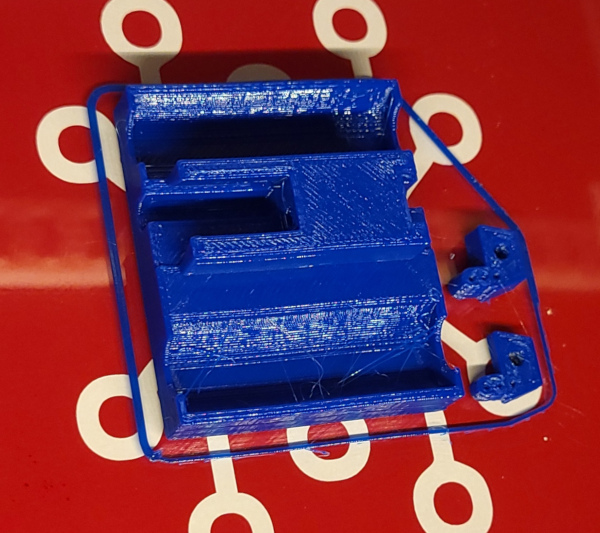
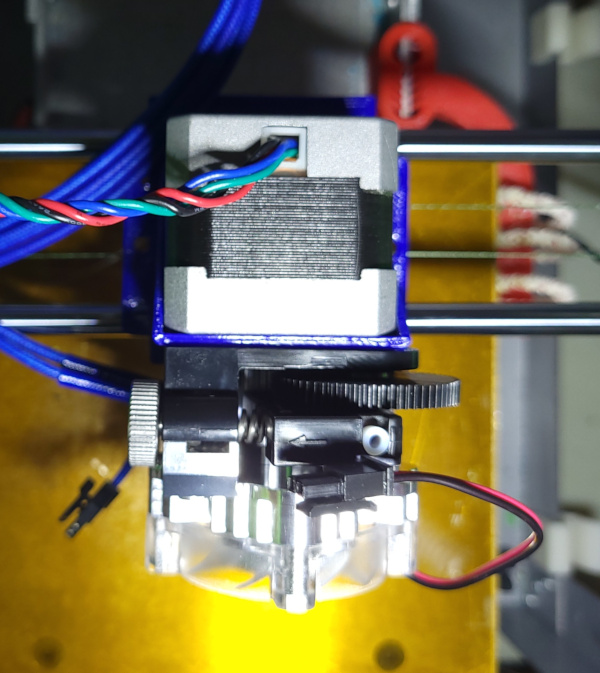
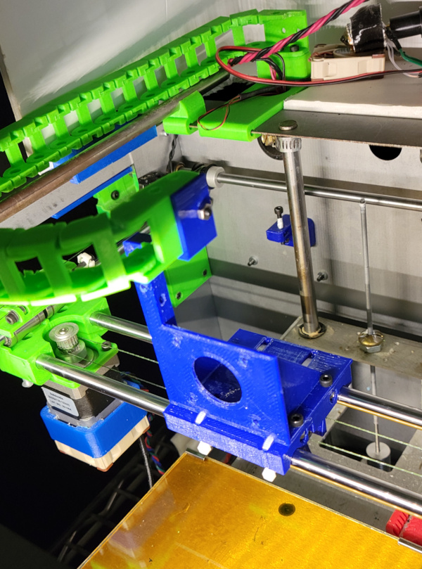
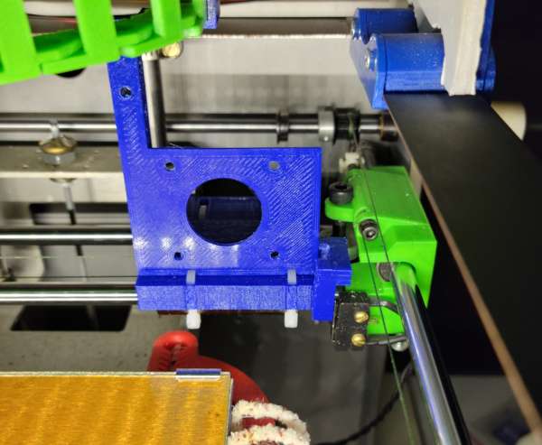
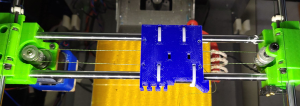
Been working on the carriage and mounting bracket for the aero. The bracket still needs the "tower" connecting to the cable chain designed, but I think the carriage is finished:
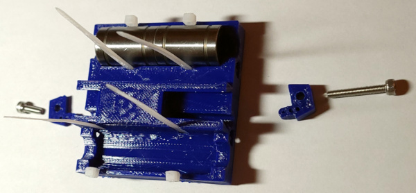
The wire ties I'll use to secure it to the bearings fit (with a little tweaking here and there with an X-Acto). I extended the channels where the fishing line is connected to the blocks to (hopefully) be less finicky to insert the blocks, and (not visible in these photos) I added nut traps in the side which will be used to bolt down the bracket.
The wire ties run over the top of the carriage:
The bracket will have matching slots on the bottom for the ties to run through so the bracket can still sit completely flat on top of the carriage when bolted down. The one wire tie moved off to the side is to get it away from the heat block so the nylon is less likely to melt :-).
Time will tell if the heat block causes me a problem. The positioning of the bracket puts it about 3mm in front of the carriage, so hopefully that's enough space. Maybe I'll put some kapton tape over the closest part of the carriage to insulate it a bit more.
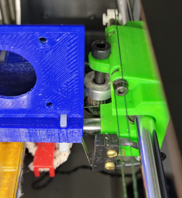
I've printed the first attempt at the bracket (almost certainly will need another one since I left off anything for hitting the X stop switch):

Might as well install this one in order to test how it fits and see if the cable chain works and the wires are long enough. Here's the final carriage back on the solidoodle with new lines installed again (the extra long channels didn't make getting the lines in less finicky):
Fortunately the mounting holes line up and the cable chain attaches to the tower (but I could only put in one bolt because I put one of the holes in the wrong place - another reason I'll need to print a new one):
If I home the print bed, the wire ties (now securing the carriage to the bearings) clear the bed with no problem:
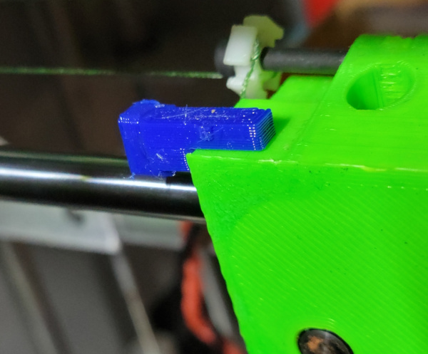
Here's where the X stop switch isn't hit:
Maybe I don't need any addition to the bracket itself. The mounting bolt for that corner is right behind the front of the bracket. I could use a longer bolt in that corner and print an extra piece to hold something to hit the stop with and bolt it down using the same bolt.
That will be a good thing to work on using this carriage for testing before I print a corrected one and move the extruder to the new bracket. I might think of other changes to make while working on this.
I've created a good initial proof of concept:
I can home X (as well as Y and Z) now without any horrible collisions:
I need to tweak a lot of things for the final version, but this works OK, and stops the carriage 1 or 2 mm before it hits. I did have to print with supports, which were somewhat painful to remove, but it came out OK.
Actually, after consideration, this is silly. I should just bite the bullet and print (and do fiddly install) of yet another carriage iteration with a wart printed on that side to hit the switch. I could make the end terminate in the exact same position as the ridiculous bolt on part (but be a lot more secure).
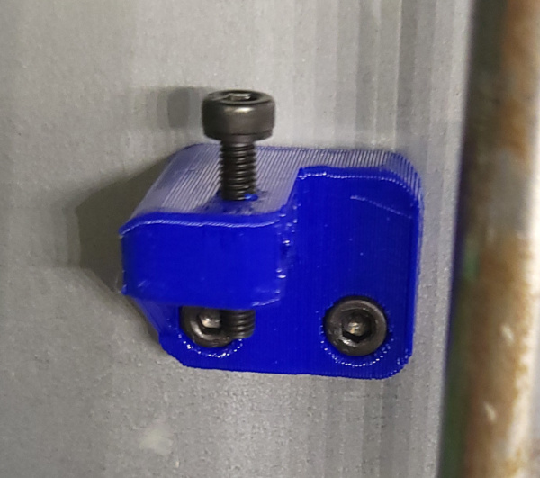
OK, carriage with proper X stop implementation is printed and installed now:

(I'm getting better at installing: a little less than moderately finicky this time :-).
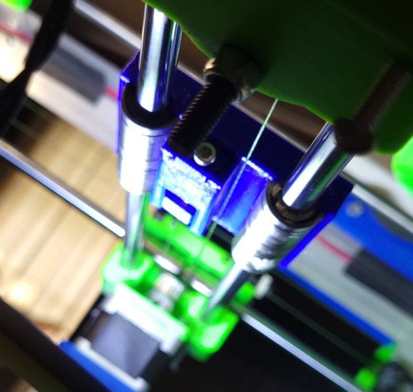
I've now re-printed the bracket with the cable chain hole in the correct location and moved the aero assembly to the new bracket. It fits fine even with the troublesome washer on the final bolt, so printing on the face with an exact layer multiple definitely helped. Here it is mounted in the solidoodle:
I can move it around OK, it doesn't hit anything in the back, but in the front, I already observed it would hit the solidoodle frame, even worse though on the left and right it runs into the brackets for the Y lines, so that takes away another big chunk of the front of the print bed (someday perhaps I can make the Y brackets smaller, but for now, I'll just lose some print bed). I asked about a slicer that can support strange bed shapes, but no luck :-). [Update: It turns out cura does support this if you are willing to write some json files.]
I have this feeling I may be printing yet another iteration of the carriage when I work out how to mount the part cooler. Perhaps some slots on the front to hold the head of M3 bolts I can use to mount the blower nozzle.
For one last addition to the carriage/bracket assembly, I intended to print a filament guide (to make sure the filament and cable chain don't mix) and secure it to the top of the cable chain tower using the utility holes I built into the tower. But now, looking at the mounted aero, the filament already enters pretty high up, may be no reason for an additional guide, maybe I'll wait till I have a problem.
I figure today will be firmware day. I tried to use the old AVRISP mkII to read the existing firmware as I had documented in my firmware page, and something now has changed expectations, nothing but errors from avrdude. After poking around on the web a while, I discovered there is new firmware for these ISP programmers, so I figured I should update it. Sigh. Easier said than done. All sorts of gibberish on the web about how to do it, but the only thing that seemed reliable is installing and running the Microchip (formerly Atmel) Studio software on a windows box and letting it update the firmware. It took what seemed like thousands of hours and ate probably half my disk, but I finally got enough installed that I could pretend to program something and have the software tell me it needed to update the firmware. Did that (which took a minute after the hours of installing junk), and low and behold, when running the avrdude command back on linux again, no problems. It downloaded the existing firmware just fine. (What a pain.) This suggests it may be able to upload the new firmware as well. Now to spend more hours uninstalling Microchip studio :-).
I also saved a screen shot of the eeprom settings so I can see what to change and what to keep. I'll want to change the extruder steps/mm now that I have a 3 to 1 extruder (and probably a different diameter hob gear). I'll also want to re-run PID tuning and save the new PID values for the new hot end.
I've successfully managed to compile and load the new firmware with the new thermistor setting. (Everything works exactly as documented in the old firmware page now that the programmer is updated.) Looking at the values reported, it seems to be pretty reasonable, so perhaps I even did it right.
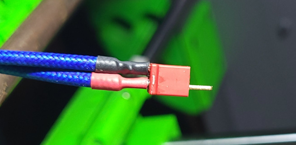
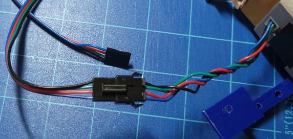
I'm now looking at getting all the wiring sorted out so I can actually test things. The weirdest plug on the solidoodle board is the connector for the hotend heater. Rather than try to find a duplicate (I don't even know the name of the connector to look for), I just cut the old connector and some short leads off the old cable and soldered the ends of the wires to the new heater cable.
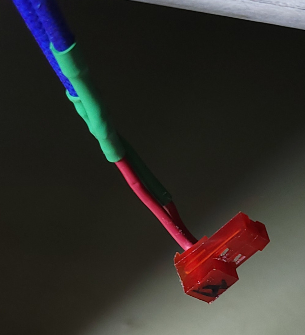
I'm using the heater cable that came with the aero, but also cutting it near the extruder and putting a Deans Micro Plug inline so I can disconnect the cable up front (same thing I did on Jiggit).
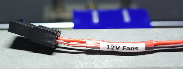
I'll do the same with the fan cables, using Molex Micro Fit 3.0 connectors since the Aero fan and thermistor use those already. Since I have another cooling fan on the extruder stepper, I'll build a Y connector to power both always on fans with a single cable cluttering the cable chain. So many things are using the Micro Fit, I'm making tiny labels and securing them with clear shrink wrap to hopefully avoid confusing all the Micro Fit connections:
I've ordered some inline JST connectors I see people using for stepper motors so I can do the same thing for the extruder stepper and everything can be disconnected up front. (And if I ever figure out how to add the part cooler, I'll put an inline connector on it as well).
One of the main advantages of everything having a connector near the extruder is that I can run all the cables through the cable chain while it is straight and easy to access, then curl it up and mount it to the extruder bracket after all the cables are in and the clips secured, and only then plug everything in.
The Y cable for running the always on fans seems to work. I plugged it in, turned on the solidoodle, and both fans spun up (in the right direction too).
Now need to make a new thermistor cable. I don't like the one that came with the Aero as it is identical to a fan cable. I'd rather make it blue or something rather than the same old red and black. There is another strange connector on the existing cable, but an ordinary dupont connector fits the pins on the board just as well.
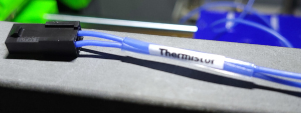
Blue it is, to match the short leads on the thermistor itself.
Once I get the stepper motor cable sorted, I should be able to plug everything in and see if it will heat up correctly. Maybe compare the temperature with the thermocouple on my multimeter.
Then get the nozzle tightening done while at high temp and maybe actually print something.
It will be a while before I can fix the stepper cable, but I can go ahead and plug in everything else and see how it is working. I compared the thermistor readings to the thermocouple on my multimeter, and everything was great till I tried to get up to 250 when the firmware told me it was overheating. I see I need to change the HEATER_0_MAXTEMP value to 285 (which seems to be a number people use for the E3D) and reload the firmware.
Firmware update seemed to work. I ran PID tuning to get get the new numbers to plug into the eeprom. Last step is getting the nozzle tightened (and putting on the sock).
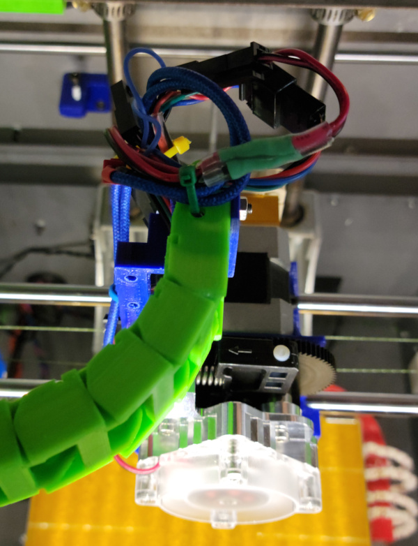
Taking the aero off the carriage after this, I see there was some melting right behind the heater block, I had hoped it was far enough away, but I guess not. Time to make a new carriage again. This time with space carved out behind the heater block. I might as well add some slots up front to secure the yet to be designed cooler nozzle.

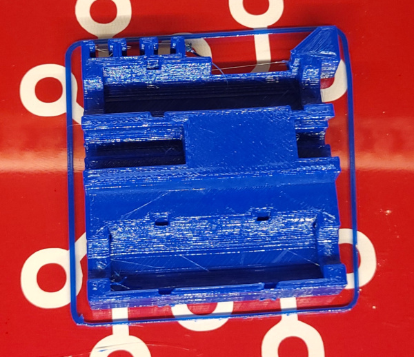
I've now modified and printed yet another carriage:
While that was printing had plenty of time to build a new cable for the stepper and put the JST connector on the stepper motor's shortened cable:
Tomorrow I can get all this mounted (probably make a part cooler cable to go in the chain so it will be there when I need it), and maybe I'll be able to print again.
New and hopefully final carriage is in the solidoodle and I'm ready to start hooking things up and maybe printing if all my cables actually work.

Grrr! Arrgh! Got everything plugged in, used M302 S0 to allow cold extrusion, and the gear just jerks around a bit, no actual turning going on. No idea what is wrong. I can turn it by hand OK. I wonder if the set screw isn't tight enough? I wish this motor had a flat section on the shaft for a positive set screw grab.
Yikes! Even more mysterious, when I manipulated a light so I could peep into the middle where the spur gear lives to watch it, everything started working again. I guess I'll just imagine it is working for now till I have some new problem. Maybe unplugging the the cable and plugging it back in was what did the trick?
However, since this is a geared extruder now, the extrusion direction needs to reverse. There is a INVERT_E0_DIR flag in the firmware, let's toggle it and see if it gets better.
Hey! It turns in the correct directions for extrude and retract now. Maybe this is the final firmware mod (though there is some software endstop stuff I want to investigate to maybe make it smart enough not to jam into something when I move it too much).
Won't be safe to move around much till I get all those free floating cables bundled up and tied down. Better do that next.
Stepper mystery solved - the blue wire just popped out of the connector. I guess I didn't grab the insulation when crimping it and the wire broke. Time to crimp all new connectors (which hopefully I can do without taking apart the cable chain).
It was finicky, but at last I got the new connectors crimped and nothing looks like it wants to break a wire off any longer. The stepper works correctly.
All the wires bundled up now so they don't hit anything. Everything still works and I seem to be able to move it around OK.
Figured out the correct setting for the extrusion rate by putting an extra piece of PTFE tubing over the filament as it goes into the extruder. I can make a mark at the top of the tube on the filament with a sharpie, then extrude, make a new mark, shove the PTFE tube out of the way and measure the distance between marks. Took about three tries to get 10mm to really mean 10mm as close as I'm likely to get. (The next time I change filament I can get rid of the PTFE, but it doesn't seem to hurt anything right now.)
I've now found that moving doesn't work right after all. The firmware has one idea of the absolute position of X max and Y max (the home positions), and the RepetierHost software has a different one. When I move from the home position, the first move is way too far because it thinks it is way farther away than it really is. I guess I should go ahead and determine the actual effective bed size I have and get Marlin and RepetierHost to agree on it.
Let's try this by setting relative motion mode G91, manually positioning at the new X0, Y0 points, then see how far I can move relative to that before hitting the endstops (I can use M119 to see if I've hit).
In relative mode, it conveniently reports when I hit the endstop during relative motion, for Y I get 126.87. For X I get 138.56 (after discovering I needed to tie down the cables a bit more so they don't hit the filament spool).
So that tells me the max range of motion I have, but the actual nozzle is off the bed on the right (and possibly in the back as well). Let's see if we can figure out those distances.
Taped a piece of paper to the bed. Traced the line of the edges with a pencil, then moved 20mm in X and 10mm in Y and marked (as well as I could see) the position of the nozzle. This tells me the nozzle is 8mm past the right edge of the bed when at X max and 6mm behind the bed when at Y max.
Using these geometries, I shouldn't hit anything when moving on the bed proper (except possibly the swiss clips in the back holding the glass on).
While I'm doing this, let's see how far Z can move. Looks like 130 is a good number. I've got more space, put I keep a lot of junk on the bottom of the printer and I wouldn't want to hit any of it some day.
Lets call X_MAX_POS 138, Y_MAX_POS 126, and Z_MAX_POS 130. Rebuild the firmware one more time.
New firmware plus new bed geometry definition in RepetierHost seems to make things sensible. Unfortunately, I just noticed that the top of the Z carriage rams into the rear cooling fan on the extruder stepper if I run Z to home while Y is all the way back. I may need to glue an extension on the back side of the left Y carriage to hit the stop switch a few mm sooner and adjust the geometry again. Since I already stop 6mm behind the bed, I won't lose any bed space if I make it hit the stop 6mm sooner.

The bit sticking out was just a handle to hold it while getting it glued. I cut it off after the glue set. Yikes! 6mm isn't enough. It still scrapes the Z carriage. I guess I need to glue a cap on the extension I glued on :-).
I think it is thick enough now, seems to be a bit of space between the fan and the carriage. Need to tell RepetierHost and Marlin the Y bed is now 117mm.
Trying to print something then killing the print, it moved too far again. Finally found the park position setting in the RepetierHost printer definition. Fixed it so it didn't try to park outside the frame any longer :-).
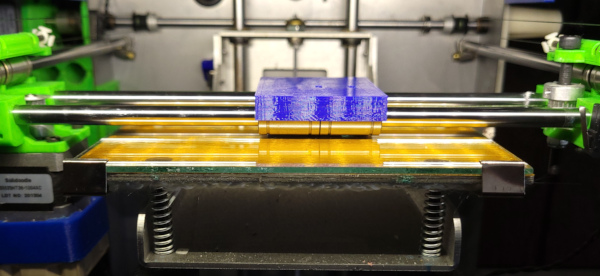
Now that it seems to know where the boundaries are, I was finally able to make my first print I didn't kill right after starting:
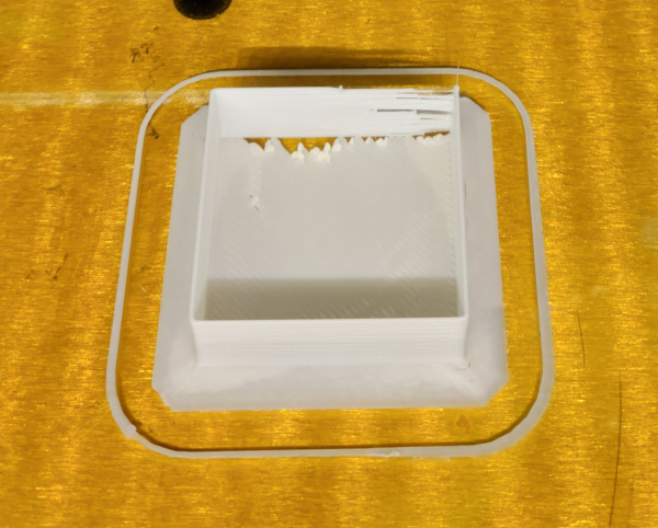
Right you are! None of those gaps are supposed to be there in the back. The print bed may not be level. Even this single layer print was curling off the bed in the back corner. The wall problems may need adjustments to retraction settings. The corner with all the gaps is where it moves Z before printing the next layer. It looks like this saga may be drawing to a close.
Got the bed leveled better, and for grins turned retraction completely off. Lo and behold! It got lots better:
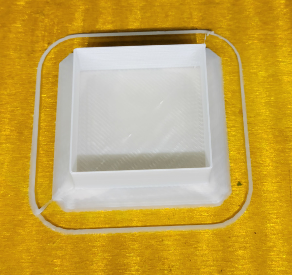
I doubt having no retraction at all is a good idea, but it certainly worked better than having the obviously too big retraction settings left over from the original solidoodle config.
Maybe it is finally time to figure out how to get cura working with enough settings to dial in to make my head explode :-).