Final Assembly
With the box as finished as it is ever gonna get, time to take apart the printer and assemble it again in the (hopefully) final form (Adam Savage in his youtube videos often talks about how often he takes things apart and puts them back together when working on a build. I hope to do that fewer times :-).
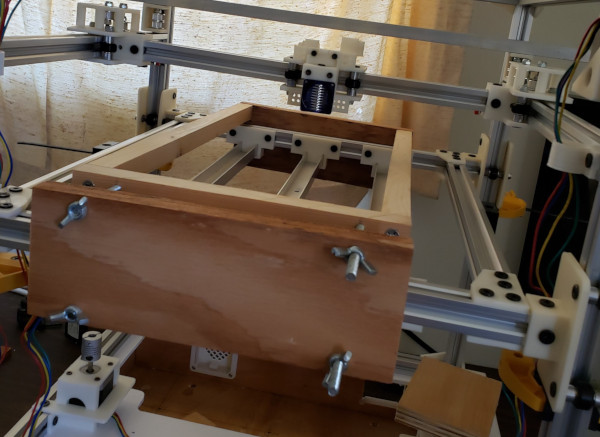
Step one is to attach the bottom rails to the box by running bolts up through the box top, putting on t-nuts, and sliding the bottom rails into place like so:
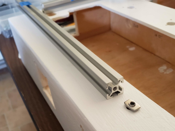
I've got plenty of slop to move the rails around, so once I got them all on the box, I spent some time squaring them up with my machinist square and making sure the corners were correctly positioned to hold the vertical rails, then tightened all the bolts to lock them into place:
I'll want to hold the covers for each half of the box under some sort of lip, so I added a couple of t-nuts to the right side I can use to mount whatever I design for that when I get around to making covers.
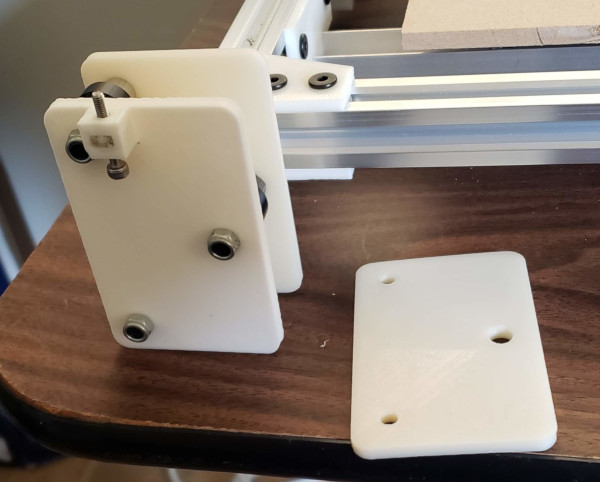
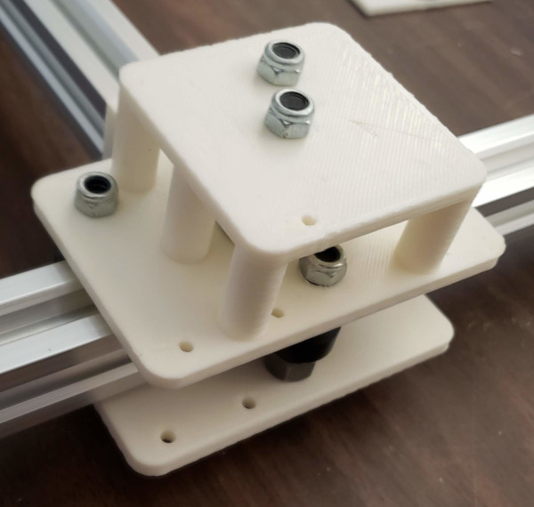
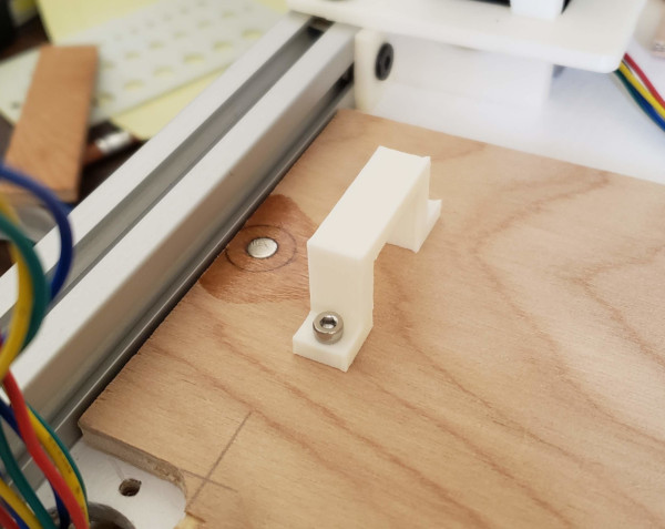
I'm replacing the old parts with new and improved parts while I'm putting everything back together. This is the new plate for the printbed support which adds a printed nut trap for a M3 nut so I can use an M3 bolt for fine adjustment of the z-stop:
I used an epoxy trick I found on the internet, spraying PAM on an M3 bolt and an extra M3 nut which clamped the trapped nut to the top of the trap. Seems to have worked. I was able to remove the bolt without it having been glued by the epoxy. I can run a bolt through the trapped nut now with no prolem, might want to add some purple Loctite to make it less likely to shift from vibration.
While the print bed was off, I also filed off the places where the first layer squishing makes it hard to adjust the supports in and out. Should be easier to properly align the print bed on the vertical rails now.
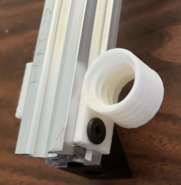
Redesigned the holders for the top of the conduit to attach much more securely with a t-nut, added them on left and right while I have everything apart:
The massively finicky job was taking apart the right Y carriage and rebuilding it with the new parts that have holes added for securing the cable chain:
Only put it on upside down once and had to take it off and remount it :-).
That's most of the new parts. Still need to remember to put the min and max z-stop switches on when completing assembly.
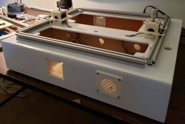
I don't want to add any of the cover plates that need wiring yet, but the fan covers can all go on now (the fans just clip in, or maybe these are just ventilation grates, not fan holders):
I learned that if you tighten the bolts too much, you can snap off the cylinder the bolt runs through (that is the weakest link between layers). So don't do that. Also learned that it is much simpler to put the back plate (with the nuts) in first while you can see through the hole, then put in the front plate and screw them together.
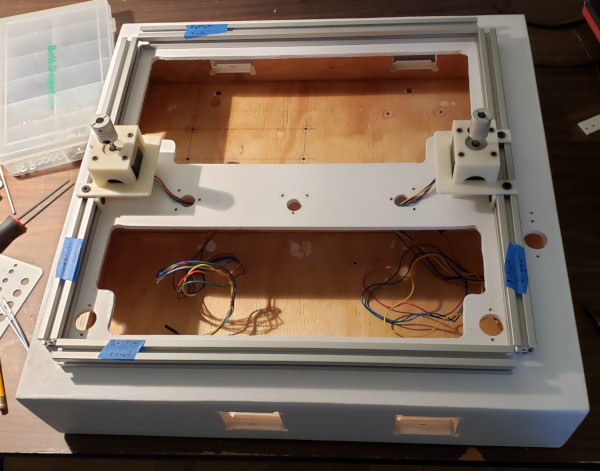
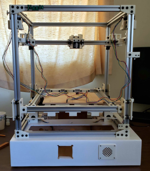
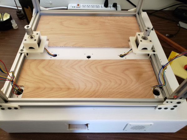
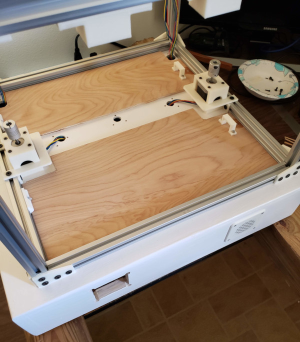
I've carefully put everything back together now, getting all the new parts on in the right order and keeping things squared up as well as I could:
Lots of tweaking still to be done. The motors go on as high as they can, so that was easy, but then the pulleys in the back need to be lined up with the pulleys on the motor. Here I've moved the X-Y assembly down and out of the way, and I've stretched some fishing line between the front and back pulley so I can adjust the back pulley to the same distance down from the top rail:
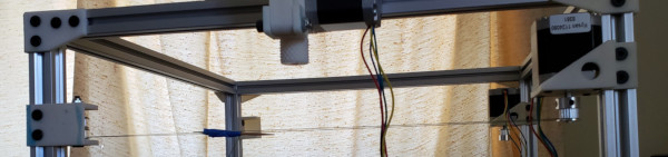
Once that is at the right height, I can adjust the assembly on the other side to the exact same height, then put in all the spacers, pulleys, and lock nuts, and hopefully be done with that adjustment.
Once I get the print bed lined up properly in the left/right plane, I'll need to adjust it in front/back to make sure the wheels are firmly (but not too firmly) seated in the vertical rails, to do that I've whipped out a custom clamp I can use to squeeze the front and back together by slowly turning the wing nuts:
After getting the outer wheels seated, I can adjust the eccentric spacers on the inner wheels to get them seated as well. Hopefully the bed motion will be smooth and stable after that.
To get things adjusted, I put together a silly leveling platform I can use (along with a cute little bubble level I got) to level the bottom rails. Then if I adjust things like the x-y rails and the print bed rails to be just as level, they should be lined up properly (at least vertically):

I used the level to get the print bed and X-Y assembly aligned as well as I could. The print bed certainly moves smoother now with no racking. Since that means I'll want to start wiring things up soon, I decided I needed covers before I put the electronics in, so I've gotten the cover pieces cut for each side:
I'll want to cut a key in each cover and 3D print a matching bracket for the cover to mate with and put a magnetic catch in the other side (a steel bolt countersunk into the box top and a small magnet epoxied into the cover). Add a handle to lift the cover with and I'll be ready for electronics.
Another problem I discovered is that my shaft adapters on the Z motors won't close far enough to grab the acme threads. I'll have to try making some shims from an aluminum can or possibly wrapping some wire around the end of the threads to make it big enough to grab.
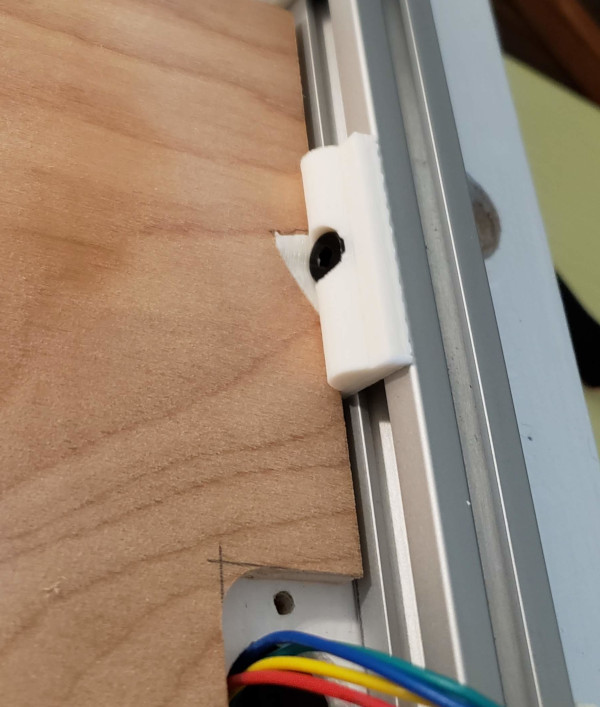
But first, finish the covers. I cut a small triangle out of the right edge of the front cover, scanned it, then extracted the shape in gimp and used that to build a model I could print for a piece to bolt to the bottom rail and position the cover (which slides under it a bit so it also holds the cover down):
That takes care of one side, the magnetic catch on the other side is next.
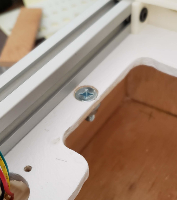
Drilled the hole in the cover for the magnet, then used that to mark where to drill in the box which allowed me to add the zinc plated steel screw for the magnet to grab:
Epoxied the magnet into the hole in the cover and added a simple handle I printed, and it works:
There is a definite positive thunk when the cover closes and it takes some force to pull it up, so this looks like a pretty good cover. Just need to do the same for the other side of the box.
Got the back cover completed:
Started on the electrical bits now. The first and most difficult part was to get the power supply screwed down in the 4 blind bolt holes I can't see on the bottom. Found that I could squish the ends of some pieces of bamboo skewers with pilers to make them press fit in the M4 holes and 3D printed spacers the power supply sits on, then was able to see the ends of the skewers as I lowered them into the holes. The printer is up on some 4x4 blocks so I could get to the bolt holes from the bottom. Pull out skewer, insert bolt, get it started in the bolt hole, and Bob's yer uncle!
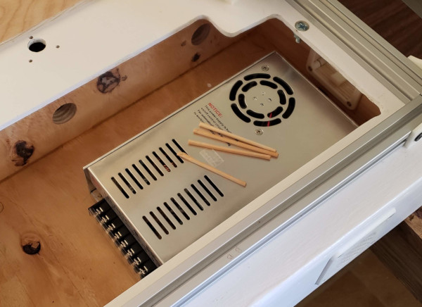
No more blind holes to deal with on anything else, and it all went it quite easily. I even hooked up the USB and ethernet extension cables to the smoothieboard. Now need to get power run everywhere:
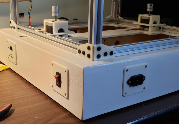
The AC power is hooked up now, the AC connector and power switch cover plates are on:
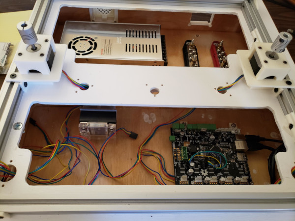
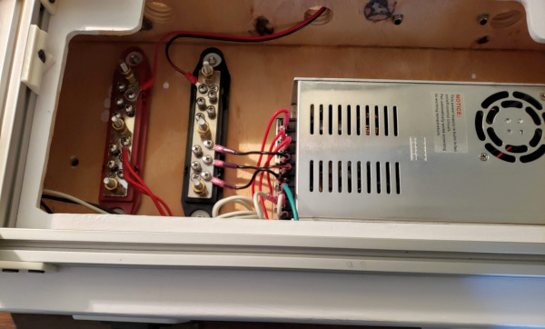
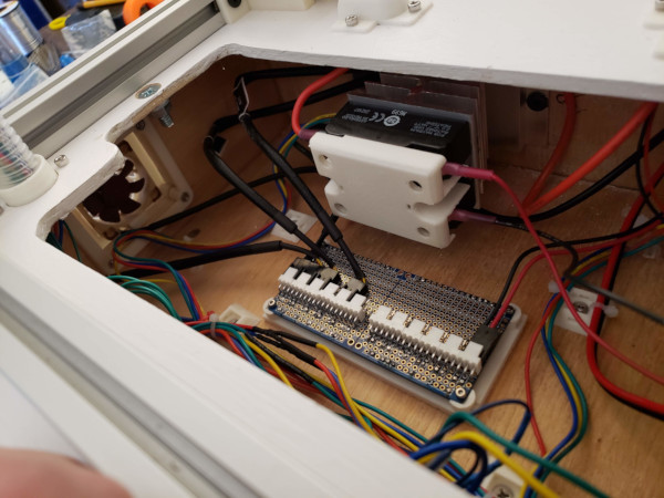
And inside the box all the AC wiring is hooked up and the 12V output connected to the overkill automotive bus bars. I've only got one connection on the bus so far - the wire that goes through the other side to provide power for the smoothieboard:
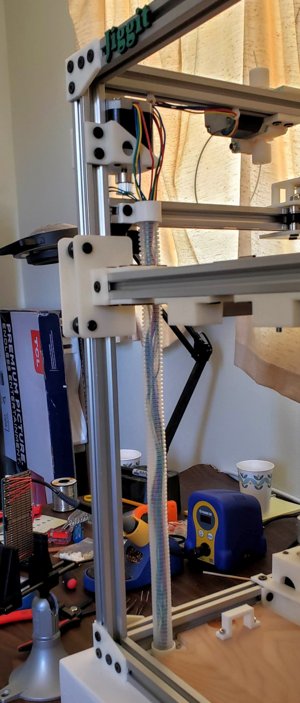
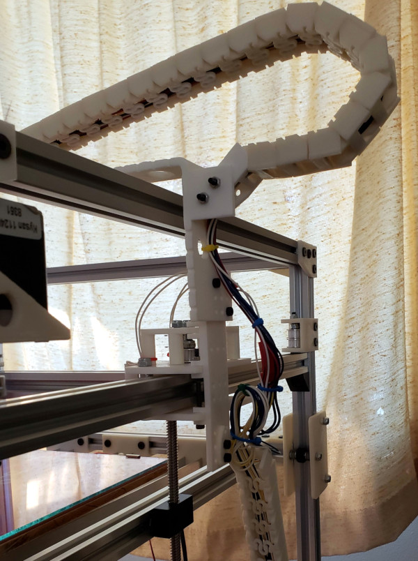
I've installed the conduit and bolted the cable chain on, this is pretty much what it will look like when done:

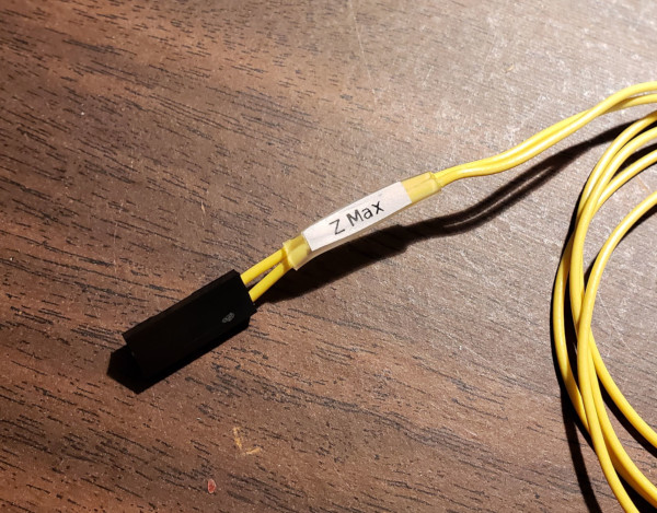
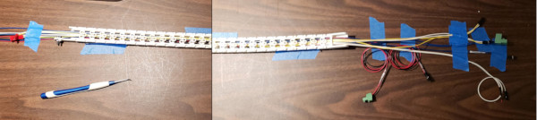
Now just need to run millions of wires around. I'm labeling them with printed labels in a tiny font slipped under clear shrink wrap. Seems to work well:
After much fiddling, I got the Z min and Z max endstops wired and verified their operation by sending an M119 command and seeing the state change as I held the switch down. It is a pain to run cables through the conduit, but I think the best solution is to take all the cables out, run a piece of string through, then pull all the cables through together. After getting proper endstop signals, I was also able to hook a stepper motor to the Z pins and observe it turn when clicked on Z movement buttons in pronterface. (First time ever I've moved a motor with this thing, good to know it works).
I'll need to run the extruder wires through my little v-slot inserts to get the wires to the conduit opening, and both the extruder and left motor need extensions soldered onto the cables. Vast amounts of wiring yet to do, and the X min and max wires will need routing through the cable chain.
Yikes! I just experimented and found there is no way I can run four wires through the v-slot inserts (they are fine for the 2 endstop wires, but the motor wires are too much for them). I guess I'll have to design a v-slot insert with a cable tie insert sticking out the top.
Meanwhile, I got the jumper built to tie together the Z motor drivers and have actually raised and lowered the bed using pronterface (the bed will clearly need more adjusting since it appears to tilt slightly when changing direction, but thats a later tweak). Also corrected the Z steps per mm so it actually moves the right amount.
Continuing to slog away at wiring. Got the emergency stop button installed and configured. I can see messages in pronterface when I hit it, and another message when I release the latched button. Made some custom cables with a fork connector on one end to attach to the SSR (for running the printbed heater) and a dupont connector at the other end to plug into headers on the smoothieboard. Ordered some 14 gauge wire to match the wire on the printbed heater so I can provide the expected current. I've got some nifty high amp RC connectors to use to make it possible to plug and unplug the printbed without taking the whole thing apart.
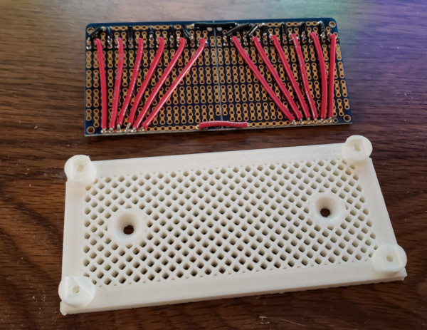
I've printed a mount for the 12 volt power distribution board I'll be adding (mostly for running fans that should always be on):
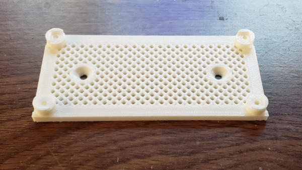
I have a bunch of right angle three pin connectors like computer fans plug into on order and I'll solder them in and hook up the power pins to the bus bars which run across the top and bottom of the board:
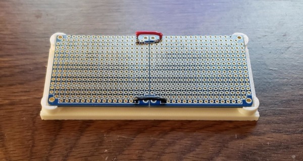
Since all the ground and 12 volt pins will be connected, I can just use one of the connectors to plug in wires from the power supply to get power to all the others. The mount has nut traps in the side for M2 nuts the M2 bolts can grab once I screw the board in place.
I've gotten the bits of the printbed all sandwiched together and installed:
The layers are held together with swiss clips which barely cover any of the top surface of the printbed so are less likely to collide with the hot end when printing than something like binder clips. I also printed a little brick to wedge into the aluminum channel to provide a place to wire tie the power and thermistor cables for strain relief.
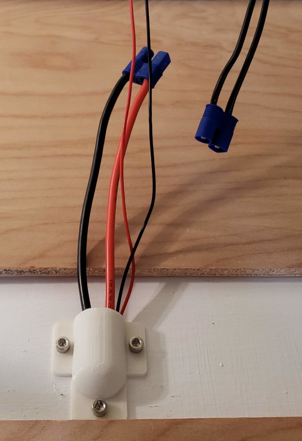
The thermistor cable was incredibly long, so I just ran it down to the smoothieboard (it even had a two pin dupont connector already on the end). The heater cable is not quite so long, so I've installed male EC3 connectors on it and will hook up matching female connectors to the power supply (via the solid state relay for control):
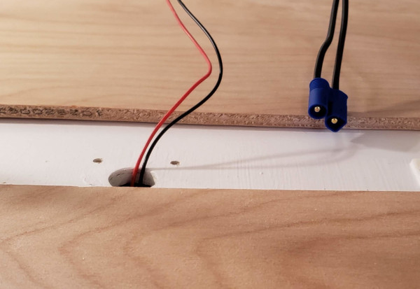
Here's a bottom view showing where I cut a hole in the center of the MDF printbed support to use a dab of thermal paste and some kapton tape to hold it on (I hope). The wires then run under the bed and out the back next to the power cable:
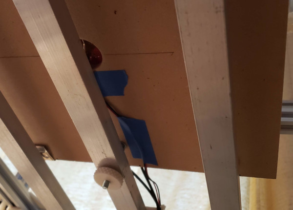
The thermistor seems to work and matches my IR thermometer readings pretty well. I'll get a better idea how it works after I can heat up the printbed.
OK, the SSR is wired up and the cables routed through the little hole covers I printed:
Unfortunately the el-cheapo SSR is toast (which is why the cable isn't plugged in). The printbed heats up if the SSR is (supposedly) switched off or switched on. At least that proves the heatbed works and the thermistor reads the ever increasing temperature (and even agrees pretty well with the IR thermometer). I've ordered a higher quality (and more expensive) SSR from digikey and will swap it in when it arrives.
Having time while waiting on parts, I decided to take out the board and solder in some additional headers for things that might be convenient. I added headers to the default kill button pins so I could use them for the kill button instead of using up a spare pin. I also added headers for the row of ground pins and the mosfet driver pins. I also removed the dead SSR while I was in the box. Unfortunately when I was putting it back together, I discovered I hadn't crimped the connectors on the Z limit switch very well, and the wire broke. Fixed that and it sees the limit switch properly again. Also tested the kill button on the new pins and it seems to work fine.
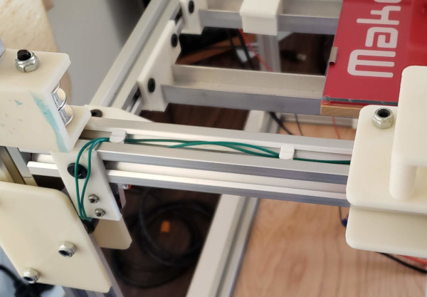
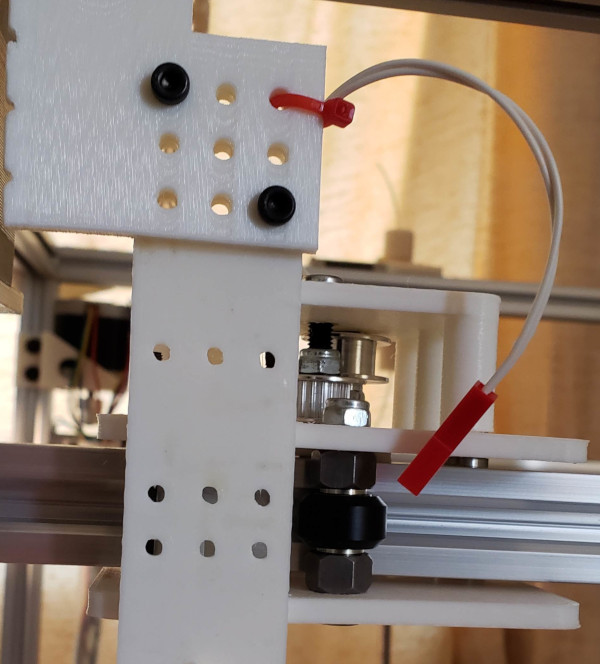
Got enormous length of wire soldered to the Y max limit switch and used my little wire-slot pieces to hold the wire down inside the vslot to run it over to the condiut where it will eventually run down inside the box and over to the smoothie board:
I ran a piece of string along the path the wire needs to go to figure out how long it needed to be (and added some slop), then cut two lengths of wire for the switch. I'll need to do something similar for the X min switch, but it will need to run down the cable chain.
My fan headers came in, so I've been soldering them to my circuit board. I got two of them fully connected and ran a cable from the 12 volt power supply to one header and successfully operated a computer fan from the other header, so it looks like I have all the pins oriented correctly, just need to hook up a bunch more headers (and take the dremel to a couple of places on the mounting board which collide with wires on the back or maybe move the wires).
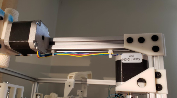
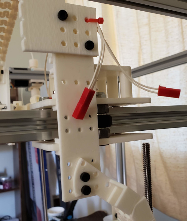
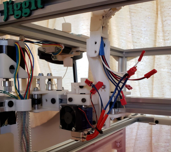
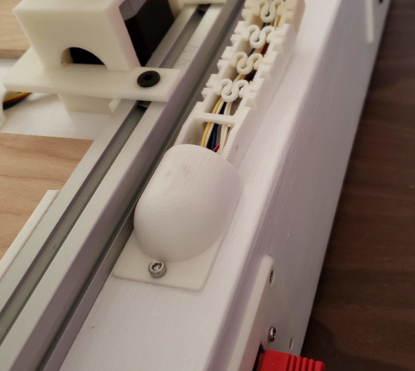
Still doing lots of soldering, but I also gave my tslot-wire-tie a try, and it seems to work to keep the extruder cables out of the way while running them over to the conduit:
My new SSR showed up, so I got it installed and can now turn the heater on and off, not just on, back to soldering again. Need to finish extending the cables on the motors that are too far away and wire up the Y min switch. Then I can tape all the wire to a string and pull them through the conduit (at least that's the theory).
Got all the cables finished that needed to be run down the left side conduit. Dropped a long piece of string down it with a nut tied to the end to make it through with the aid of gravity. Taped the ends of the various sets of cables to it at intervals, then very carefully pulled the string through. Lots of attempted tangling at the top (which is where the care came in), but it actually worked really well. Hopefully I never need to run anything else through that conduit, because it is pretty well packed now.
Got connectors crimped on all the wires, got everything plugged in, and (as long as I had wires and crimping tools out) made some dummy jumpers for X min and X max to make it think those endstops were not hit, and by golly I can move all the motors. I even ran a piece of filament through the extruder and I can see it move when I tell it to extrude filament. I guess I successfully soldered on the extensions.
Now I have the hot end and X min and max to hook up for real with all the wires running through the cable chain. Probably finish the fan header board first since it is already started.
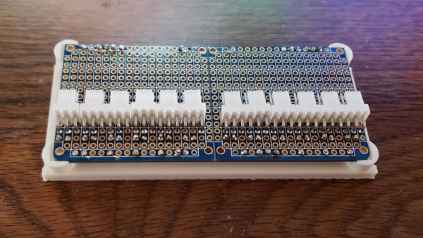
The dozen fan headers are now all soldered to the circuit board. The dremel only took a few seconds to sand away the bits of support that collided with wires:
The board now fits solidly on the mount and is ready to be installed inside the box (after I get the wires already in there out of the way).
I got the wires a bit more organized inside the box and installed the board with the dozen 12 volt fan headers:
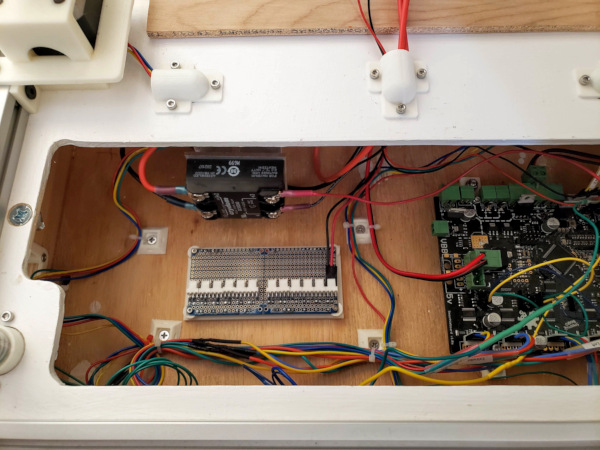
I plugged in the power to one of the headers, then I tested everything again, and it all still seems to work after fiddling with the cables, so I didn't manage to break anything or yank out any connectors.
I got the initial fiddly work of assembling the hot end done, need to make some temporary cables so I can hook it up off to the side and get the final nozzle tightening done while it is hot (and test the heater and thermistor, maybe compare the temps with the thermocouple my multimeter came with).
Test cables are made and plugged in, the hot end is mounted on vise for testing and arranged so I can easily get to the block and nozzle with wrenches for final tightening when I heat it up:
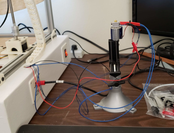
Seems to work. I ran PID autotune, updated the values in the config, then cranked the heat up to 280 and gave the nozzle a final tightening. My hot end work is done till I get the connectors I ordered for the heat cartridge cables to make it more convient to plug it in.
I guess running lots of wires through the cable chain is the next step (though I'll probably wait for the connectors so I can make the heater cable and run them all through at once).
Other random things I've done: Found a CAD model of the SSR cover for the specific SSR I bought, downloaded it, fiddled with a lot of online repair and conversion tools and was able to print a cover (not clear like the real one). Also got fans installed in all the fan ports in the box (it is a little noisier than it was, but the power supply fan was already pretty loud):
Did PID tuning of the bed heater (which may not make a lot of difference, but why not). Finally, as long as I had a test piece of filament in the extruder, I marked it with a sharpie, then extruded 20mm worth, and by golly the default settings apparently match my extruder, because as near as I can measure, exactly 20mm of filament came out.
I've been thinking about getting all the cables run through the cable chain, and I think my best bet is to carefully measure how much cable I need coming out of either end and how much separation there is between the two chain segments (adding a bit of slop, of course), then unscrew the cable chains and lay them out flat and remove all the clips. Tape everything down so it doesn't shift and draw the locations of the ends on some cards which are also taped down at the ends. Then I can build the cables in place on a nice flat surface (kind of like the way a wiring harness is built for an airplane, but much simpler). Probably need a series of weights along the way to keep the cables down in the chain and not curling up everywhere (AA batteries are probably heavy enough if I tape a cable chain width piece of cardboard to them). Once all the cables are in place, put all the clips back and screw the chain segments back to the printer. Sounds simple enough, I wonder what will go wrong :-).
The X min and max endstops don't really work with the above scenario since I need to solder the switches and run wires without connectors cluttering them up through the vslot. I think the thing to do for them is divide the cables into two segments. Stick the little JST connectors I have on the ends of the switch wires after running them only as far as the end of the chain that comes up to the Y carriage. Then I can lay out the second length of cable for them while I have the chain out of the printer and put mating connectors at that point. I can put male connector on one switch and female on another so I can't confuse which one to plug in where.
Important thing to remember when I start filling the cable chain: I put male JST pins on the X min switch wires that extend across the printer through the vslot and out the Y carriage. Therefore I should put female pins on the X min cable that comes up the cable chain from the smoothieboard:
So when I wire up the X max switch (much simpler since it is already on the correct side of the printer), I'll want to use female pins to distinguish the ends of the switch cables.
The X max switch is now wired up and has female pins. Just gotta keep it straight when building the cables and I'll be all wired up (though who knows how long it will take to get the connectors I ordered for the hot end heater cable):
Maybe I'll see about setting up a zprobe while waiting. I've got the incredibly bulky renishaw probe, but a simple switch mounted on the carriage would probably be fine for manual bed leveling. (But I also want to mount a PWM cooling fan as well - not sure how much junk I'll be able to clutter up the carriage with.)
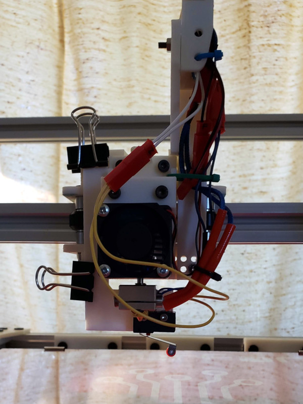
Here's the zprobe bracket I printed with a switch screwed on:
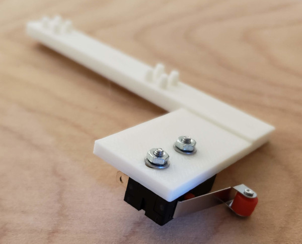
The bumps printed on it engage with the holes in the carriage to lock into place and be held with binder clips. Here's what it looks like on the carriage:
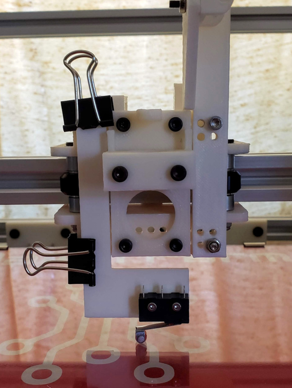
That makes one more wire pair I'll need to run through the cable chain. The idea is to put this on the carriage, use the G30 gcode command to see how far the bed has to move to hit the switch. Do that at multiple points and adjust the leveling screws till it moves the same amount everywhere, at which point the bed must be level.
Thought of another thing to test: I wired a 40mm fan to the small mosfet controlled by pin 1.22 (this one already gets power from the motherboard, which is plenty good enough to run a fan), changed the config to tell it the fan uses 1.22, then did some testing. The fan really did go on and off, and setting it to a lower speed also seemed to produce a less powerful breeze. Seems to work.
Got the micro Deans connectors I ordered for the hot end heater connection and seem to have successfully soldered them onto the hot end and the cable:
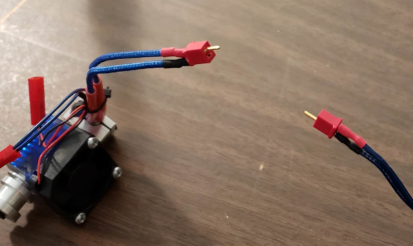
Didn't really need the polarized version, but bought some extras and figured polarized would be the most useful to have around. I've started filling up the cable chain now but it is slow going:
I use the layout to unspool the appropriate length of cable, attach the connectors needed at the hot end side, run the cable through the chain using some press fitting pieces of cardboard to hold it down, then finally attach the connectors I need at the other end. Hopefully I've measured the excess cable I need at the ends correctly :-).
After much fiddling, finished making the cables, adding them to the chain, and putting all the clips back in the chain:
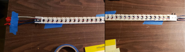
The little dental probe is very handy for testing the clips to make sure they are in solidly and adjusting the position if they missed the hole.
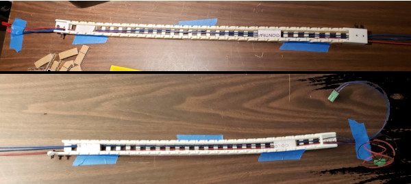
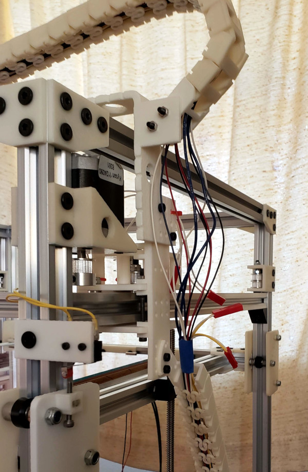
Got the chain screwed back to the printer (tape was involved to hold it in place while getting bolts in). Then I gradually got everything plugged in and tied down. Here are before and after pictures of the ends of the chains:
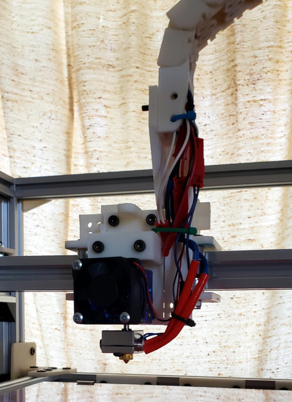
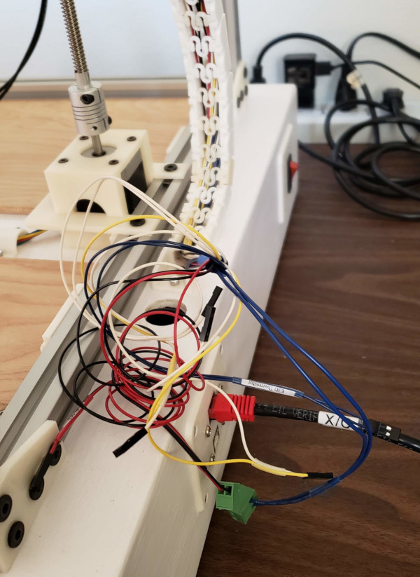
I dragged all the excess cable into the middle of the chain on the Y carriage since there isn't much of anything to get in the way out there. Fortunately I didn't make any of the cables too short. Everything seems to move just as smoothly as it did before getting all the wires in place. I've been testing everything and it all seems to work.
Possibly the very last cable: I soldered wires and crimped a connector for the Z probe switch. The probe seems to fit fine just behind the hotend and using G30 really works to measure the bed height at different points. I now have the bed reasonably leveled:
It may be time to tell the smoothieboard I have a corexy printer and run the drive belts (I hope I have a long enough roll of belt for both of them :-).
OK, I got the belts run around all the right pulleys and my little wedge gadgets seem to work great for holding the ends and tightening the belts:
I fixed the config file to say I have a corexy machine and told it to home to the left front corner (X, Y, and Z min positions). A couple of small test moves showed that it was going the wrong way, so I reversed the sense of the two top stepper motors in the config file, and that made it move the right way. Time for the big test, pushing the home button: