My Problems
A log of adjustments and calibrations I have made and pictures of things that went wrong.
- Curling Prints
- Y-Axis Adjustment
- Calibrations
- Filament Friction
- Klunk?
- Repetier Host
- Remixing STL Files
- Ceramic Bed
- Slicer
- Bed Heater
- Rants
- TARDIS
- Firmware
- Weird print artifact
Curling Prints
The first thing I tried to do was print a little model I made in openscad of a logo made from my initials:
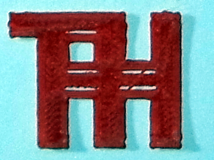
As you can see from the shadows, the print curled up off the kapton and I stopped the print early. I tried this several times adopting various suggestions about cleaning and leveling and wot-not and never got anything to stop the curling till I tried the one thing everyone seems to eventually wind up with — A glass bed and AquaNet hairspray. That worked like a champ.
I did eventually see that I could still get curling problems on larger parts, so I started using a brim and also built a case to keep the air conditioner from blowing right on the print bed. So far that combination has been working well. If I get curling now, I know it is time to clean off the glass and start with a fresh layer of hair spray.
For really tough objects that have a tendency to curl no matter what I do, I've taken to setting the 1st layer speed quite slow (maybe 40 to 50%), printing a brim, then after the brim is mostly printed, I paint the corners with secret sauce (a 50-50 mixture of Acetone and MEK with some ABS dissolved in it). The slow print speed gives me time to get in there with a brush without being knocked around by the print head. I haven't ever had a print curl up on me when doing this. It was very effective on the large TARDIS side panels.
Y-Axis Adjustment
I can now print the whole model without it curling up, but the geometry is screwed up. There are gaps that aren't supposed to be there and the horizontal and vertical bars that make up the part are supposed to be the same size, but the horizontal pieces are obviously too thin:
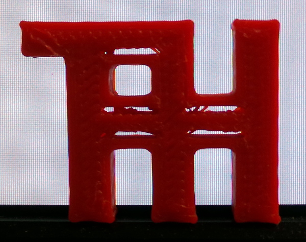
I asked about my gaps in this soliforum thread and the reply said it might be more of a slicer problem, so I tried some variations in the slicer and used netfabb repair, but to no avail. The gaps were still there. At this point I decided I had to try the scary y-axis adjustments from the solidoodle troubleshooting page:
That seemed to do the trick:
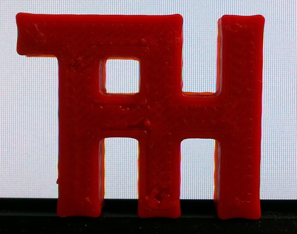
The biggest problem with following the video is trying to understand what you are actually trying to accomplish. He says what he is doing, but not why he is doing it :-). I eventually decided that one of the critical points is to get the belts lined up so they are exerting force only in the direction they are supposed to go, not sideways against the edges of the pulleys.
Calibrations
Z-Stop The first thing I tried to calibrate was the Z-stop. Obviously it will be changed by adding the glass bed, so my first attempt used a small piece of thin brass sheet I had to poke under the nozzle and see if it felt like the same resistance everywhere.
This is not a very accurate technique, and it gets less accurate if the bed isn't level since the space will change from point to point.
I certainly got things a lot better than they were to start with, but it was never a very satisfactory way to adjust things.
A slightly better technique seems to be to lower the bed, put the shim under the nozzle, then home the Z axis. Now you can see how much resistance is required to pull it out. This is the only way I've found to use a paper or brass shim with moderate success.
Recently I have started using my digital calipers to measure the thickness of any skirt or brim that I print and see that it is indeed real close to 0.3mm. That seems to be a much better technique to check the level than trying to estimate how easily a shim pokes under the nozzle.
It would probably be even easier to dial in if I printed one of pcpoirier's M3 screw travel indicator to use when changing the Z-stop screw, but I haven't tried that yet.
Once I finally got the bed level using my Dial Indicator Rail Mount, the best way to set the Z-stop seems to be just watching the brim print. If it doesn't stick at all and the threads are mostly round, the nozzle is too high. If it flattens out, but printing the next inner layer of brim pushes the previous brim around (this especially seems to happen when it is navigating around a corner), then the nozzle is too low and the brim is squishing out wider than expected. I just watch for this, and kill the job if it happens, tweak the Z-stop, and start the print again.
Another good technique to decide on the Z-stop setting is to print a calibration cube with a single layer on the bottom. If the bottom appears solid and uniform with all the lines nice and straight and sticking together, the Z-stop is probably at the right height.
Another tip: I can't really tell when the hex driver is actually in the Z-stop bolt socket and rotating it. I painted a couple of white dots on the head of the bolt to make it easier to see when it actually moves (I had a white nail polish pen I bought once to repaint the worn off letters on a keyboard and was surprised to find it hadn't dried out). While I was at it, I painted a line on the extruder gear so I could see it rotating.
Extruder Several good web pages talk about how to calibrate your extruder. Ian Johnson's Extruder Calibration page is one, John's 3D Printer Calibration covers several calibrations, not just the extruder.
I used a bit of masking tape on the filament and a ruler to get a better number dialed in, but it could be more accurate, and I talk about better techniques in the Extruder Flow Calibration page.
I also measured the filament diameter, and found that the solidoodle filament I'm using at the moment really is pretty much exactly 1.75mm, so I didn't need to change that number.
X and Y I used MrJohn's A Better Nickel Calibration Test to check and adjust the steps per millimeter in both X and Y direction, and got a pretty good final version printed:
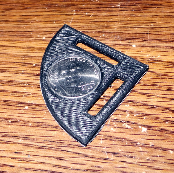
Important note: The nickle test will help get you in the ballpark, but the nickel test object is too small to show up a tiny variation that will grow across a large object. My nickel calibrated printer couldn't print My Electronics Cover because the screw holes didn't come out in the right places (so that turned out to be a good calibration object as well).
Having done that, I suspect the best way to get the most accurate X and Y stepper settings is to punch a bunch of random holes in a large enough piece of thin cardboard to cover the printable area of the bed, scan it with a flatbed scanner and use that scan to generate a model to print, then print that model and scan it with the same scanner settings and compare it with the original in gimp to find out how much you need to scale in X and Y to get the printed part to be identical.
Bed Level In My Gauge Mount I build a ridiculous mount for a dial indicator that allows me to level the bed a lot better than I had previously done. I also used jon_bondy's Yet Another Solidoodle Thumb Screw to modify the bed so I could move the leveling screws. (I printed the short version since I didn't have much space.)
I no longer use my original mount, I now use my Dial Indicator Rail Mount, which is harder to use because you have to keep taking it on and off the rails and moving the carriage out of the way, but is vastly more accurate than anything I ever mounted on the carriage.
Filament Friction
I was printing along OK for a while, then (without making any changes) I started to see this nonsense in the layers of filament:
There are gaps and thin stretched out spots. I don't seem to have a clog. If I extrude filament into space I got a nice even vertical thread of filament coming out of the nozzle, so I poked around for a while, and finally searches turned up a pointer to Filaments not Touching.
It mentions that the most common cause is excessive force required to pull the filament from the reel. It is certainly possibly that I've worked my way down to the more tightly packed inner layers of the spool, and by golly, if I print the part again and spend the print time turning the spool by hand to make sure the filament is always slack, then the part comes out like this:
This eventually resulted in Solidoodle Spool Mount which uses garage door rollers and top feed to reduce friction and avoid dragging the filament around corners.
I also ought to check for dust clogging up the sprocket which might make the filament more likely to slip.
Klunk?
Lately, the printer has developed an occasional klunk! noise, which mystified me no end till I started checking everything for movement and found that the pulley up in the top corner of the front of the printer was loose and could slide back and forth making exactly the kind of klunk I was hearing. I obviously need to do the Y-Axis alignment again and secure the setscrew [wrong] in that pulley while I'm at it. Hopefully that will eliminate the klunk till something works loose again.
Upon further review, that pulley is supposed to be loose, but I suspect it was still the source of the klunk. I did the Y-Axis alignment again, and I think it has stopped klunking now (maybe I'm getting better at it).
Nah, the klunk still sometimes reappears. I'm starting to suspect the various pulleys aren't completely parallel, but haven't figured out how to test it or fix it if it is busted.
In fact, I am less and less sure about what might be klunking, I can't seem to correlate it with anything.
Repetier Host
I also had a few issues with the repetier host software until I learned what was going on.
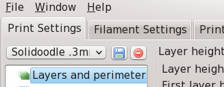
My first issue was that for some reason I couldn't see the dad-gum connect button. Maybe I couldn't find it because the icon is the universal on/off switch icon and nothing in my brain registered connect for that icon? Maybe I couldn't find it because I was expecting a connect option somewhere in the printer menu? Maybe I couldn't find it because it wasn't anywhere near the printer settings button? Maybe I couldn't find it because it wasn't on the manual control tab where you actually need to be connected? Maybe I couldn't find it because the Repetier Host docs on connecting go through the printer settings in detail, but never mention a connect button? Or maybe I'm just blind as a bat? Anyway, it is near the top left corner under the file button:
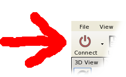
Having found it, I still needed to discover that I had to use the pulldown option to distinguish between the old leftover default printer and the new solidoodle2 printer I just defined. I eventually took care of that permanently by deleting the default printer, so now there can be only one to connect with.
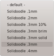
Another problem was configuring slic3r. When goto the slicer tab to change the configuration, you can see the current selected configuration is named "Solidoodle .3mm brim".
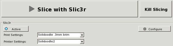
The slic3r config dialog that comes up looks like this:
The name of the config it is editing is too short to show the whole string. For the longest time, I was assuming I was editing the configure I had selected back in repetier host, but no, you have to actually pull down the list of configs to find out what the current one actually is:
Until I discovered that, I could never figure out why my changes always seemed to disappear :-).
Remixing STL Files
Several times I've wanted to modify objects that were only available as STL files. Openscad can import STL, but to use the existing STL you need to know exactly where the object is and where the bits you want to cut and paste are within the object.
The netfabb basic tool (which you can get for free) can do object analysis to tell you the position and dimension of objects.
To pick dimensions out of an object, I use the repair tool, which allows me to select individual triangles in the model and turn them into separate parts. I can then use the analysis tool on that 1 triangle part to discover exactly where it is within the model.
It is cumbersome, but does indeed provide the exact dimensions you need to pick parts out of existing models.
Ceramic Bed
I've moved all related info to this Ceramic Bed page.
Slicer
I ran into some problems with slicer software in my PCB Vise work. The eventual solution was netfabb Cloud Service.
Bed Heater
The print bed takes a while to heat up (and even more time if you add glass or ceramic), so I'm investigating a Bed Heater Upgrade
Rants
Grrrr! I thought linux always had out of date and obsolete docs. Linux has nothing on Solidoodle. They keep tweaking the design (wooden bed to aluminum bed, .35mm nozzle to .4mm nozzle, Sanguinololu to Printrboard motherboards, etc.) Virtually all of these things require tweaks to the settings you should use for best prints, but all of the documentation in the FAQ or WiKi is totally random hit or miss. Each paragraph reflects whatever may possibly have been true at the time it was written and is never revised or updated. The adjacent paragraphs may be completely bogus and conflicting. It is virtually impossible to discover what settings you should actually be using for the printer you actually received. The same is true for the pre-packaged software. The built-in settings are whatever was true at the time the package was created and is never revised so using their software configuration for your new solidoodle may be a completely rotten way to print.
TARDIS
I've been having an interesting time printing a TARDIS. I don't really understand what is going on here yet. [OK, my main problem was fixed with the Solidoodle Springloader].
Firmware
If you decide to load new firmware, it can be tricky. I've documented my procedures in the Solidoodle Firmware page.
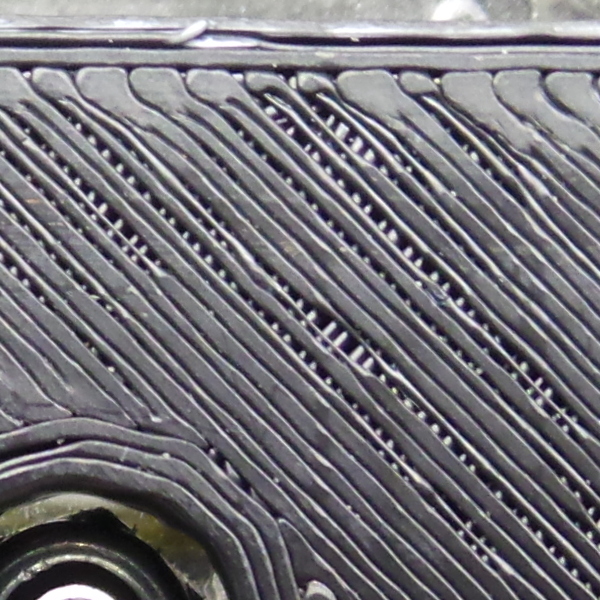
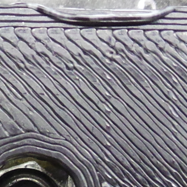
Weird print artifact
I have no idea what this might be. I printed 4 big hex shaped blocks at once for some supports in a project I'm working on, and this weird diagonal groove with raised edges appeared on one of them, then near the top, switched to a different one.
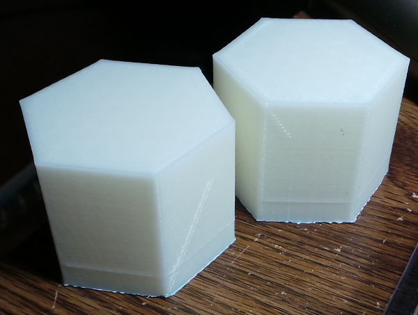
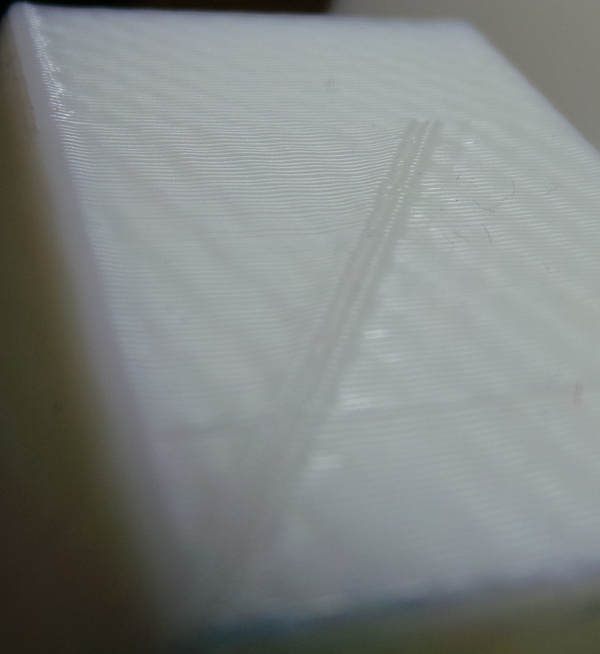
The little horizontal ridge near the botton on all 6 sides of all 4 blocks I can imagine is the Z axis not moving up far enough for some reason and causing that layer to squish out a bit, but the diagonal artifact, I can't explain.
Go back to my main Solidoodle page.