PCB Vise
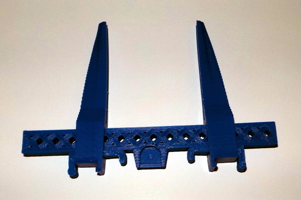
Started with PCB Vise from thingiverse (and subtracted off a grid from the bar to see if that would keep it from curling - it still curled a bit at either end, but not nearly as badly as my first try):
Wrote some more openscad code to scale it up a tiny bit to provide slack and subtracted it from a cylinder to produce a piece to grab it:
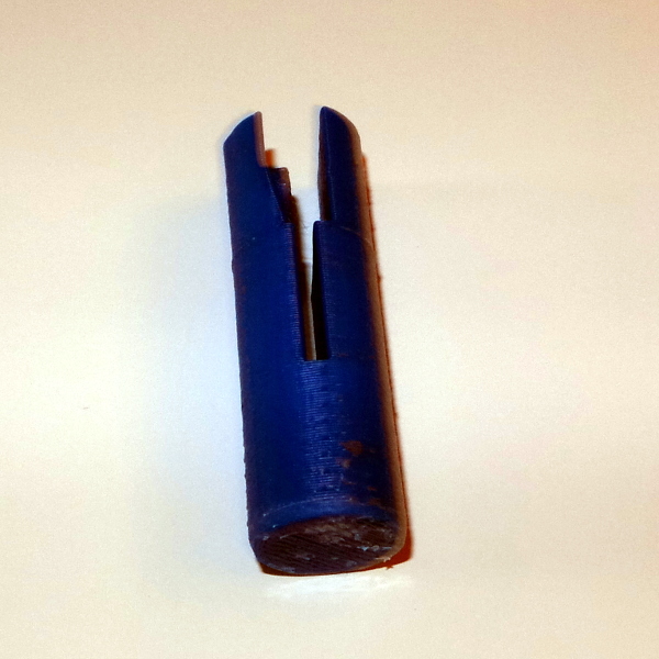
Like so:
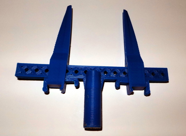
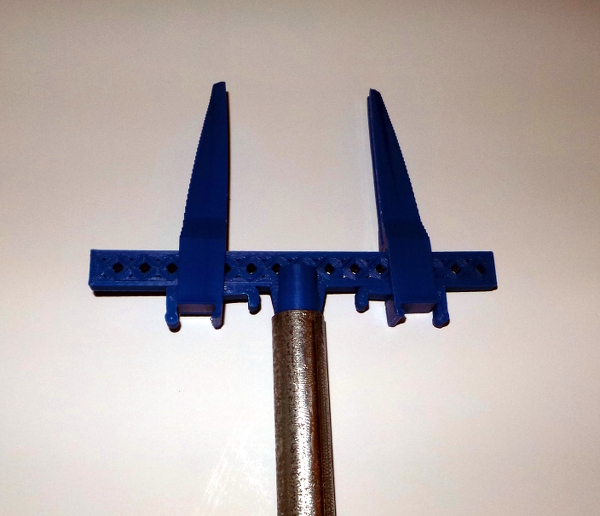
That piece, in turn, can be wedged into a bit of electrical conduit to get the vise mounted on an arm:
That was sort of OK, but I really wanted it to be a tighter fit in the conduit, so I changed the top half of the cylinder to be a very slight cone with the sides flattened so any squeezing of the cone would clamp the two sides tighter together rather than merely jamming in the conduit. Here is the openscad code:
bw=12.8;
bl=140;

gw=3;
gs=gw+6;
gn=3*(bl/(gw+gs));

module grid() {
   union() {
      for ( i = [0 : gs : gn * gs]) {
         translate([0, i, 0])
            rotate([0,0,45])
               cube([bw*3,gw,20]);
      }
      for ( i = [0 : gs : gn * gs]) {
         translate([0, i, 0])
            rotate([0,0,-45])
               cube([bw*3,gw,20]);
      }
   }
}

// A remix of the bar with a grid through it to try and get it to print
// without curling (it still curled some).
//
module bar() {
   difference() {
      rotate([0,0,45])
         import("PCBviseBar.stl");
      difference() {
         translate([-(bw-6)/2,-(bl-6)/2,-20/2])
            cube([bw-6,bl-6,20]);
         intersection() {
            translate([-(bw-6)/2,-(bl-6)/2,-20/2])
               cube([bw-6,bl-6,20]);
            translate([-13.5,-90,-10])
               grid();
         }
      }
   }
}

tubeid=15.82-0.05;
tubelen=50;
sloth=2;

// A cylinder designed to slide into a piece of electrical conduit and
// and grip the mount point on the bar so the conduit forms an arm to hold
// the clamp. (Note: Conduit seems awful variable in size, best measure
// the piece you are planning to actually use before printing - mine measured
// 15.82mm inside diameter).
//
module conduit() {
   rotate([0,90,0])
      difference() {
         union() {
            rotate([0,90,0])
               cylinder(h=tubelen,r=(tubeid/2), $fn=24);
            intersection() {
               rotate([0,90,0])
                  cylinder(h=tubelen/2,r1=((tubeid+0.4)/2),r2=(tubeid/2),$fn=24);
               translate([-1,-tubeid/2, -(tubeid+10)/2])
                  cube([2+tubelen/2,tubeid,tubeid+10]);
            }
         }
         translate([0,0,-(5.71/2)])
            scale([1.01,1.01,1.01])
               rotate([0,0,45])
                  import("PCBviseBar.stl");
         translate([0,-(tubeid+2)/2,-(sloth/2)])
            cube([tubelen*2/3,tubeid+2,sloth]);
      }
}

conduit();
PCBviseBar.stl is the STL file imported by the newbar.scad file above.
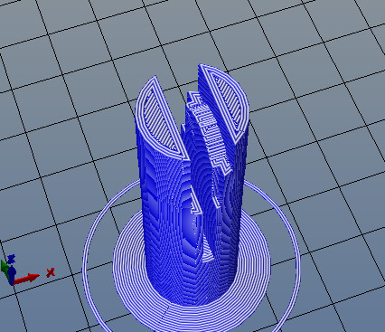
This is where mysterious problems cropped up with the slicer. The first version with a straight cylinder printed fine, but the cone shape totally screwed up slic3r. Instead of the ramp shape to match the bar, it printed a square step. Looking at it in the Repetier Host gcode preview, that was what slic3r really did:
Having heard how much better kisslicer was at problem parts, I tried it, and it was weird in a different way with a funny little blob off the side and sawtooth edges on the sloped part.
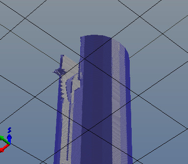
It did complain about degenerate triangles, so I guess it doesn't like hanging around with degenerates. I then tried sending the STL file through the netfabb cloud service, and the version I got back finally sliced OK in slic3r, so that ended my first kisslicer experiment.
I reported this as issue 541 on the openscad bug list (just in case someone wants to check it out).
Anyway, I now have a part that looks pretty much the same as the one above, but this one squeezes into the conduit better for a more solid grab.
Now I have to work out what I want to do to hold the conduit in convenient adjustable positions...
Go back to my main Solidoodle page.