New Y Idlers
I've now started the project to make new Y idler brackets to take less space and get some of my print bed back.
I'l clearly be printing these on Jiggit, since I've already taken off the old Y brackets (one of them was pretty badly cracked, so they'd have had to come off soon anyway).
I took this opportunity to remove the bearing that was no longer used on the Y rod (from the obsolete Y Rod Bearing mod).
With the old brackets out, I should be able to measure all the dimensions I need for the new brackets.
My current plan is to use new (smaller) bearings I had from the batch I bought for Jiggit. I'll use the longest flat head 5mm screws I have and run them outside the frame through supports that butt up against the frame. There will be just enough of the screw inside the frame to allow the bracket to be screwed to the existing holes in the front of the frame.
After carefully measuring things, then adjusting my measurements after printing test pieces, I finally got a test piece that allowed me to see the best way to fit the new idler bearings:
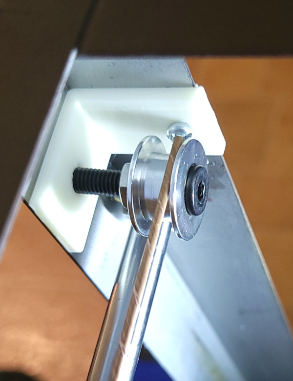
The nice straight piece of copper wire allows me to check that the front and back bearings are lined up and the path between them runs through the same plane as the fishing line attachment screws on the Y carriage:
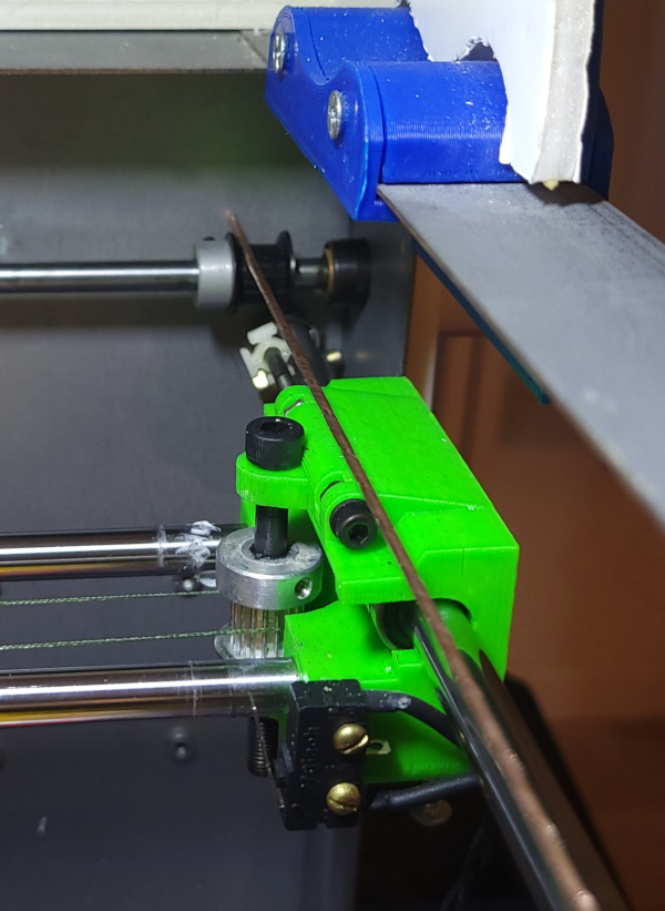
Now I just need to design the real bracket with a more solid structure that holds the bearing in the same place.
I'm thinking I might be able to run a vertical hole through the back behind the bearing so I can thread the fishing line through it more easily then reach into the bracket and grab it with a hook to pull it through (it was always a pain with the old brackets).
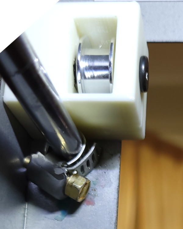
After a few errors in my openscad, I finally got the bracket printing properly and installed. Here's the view from the inside of the new bracket:
And the view from the outside:
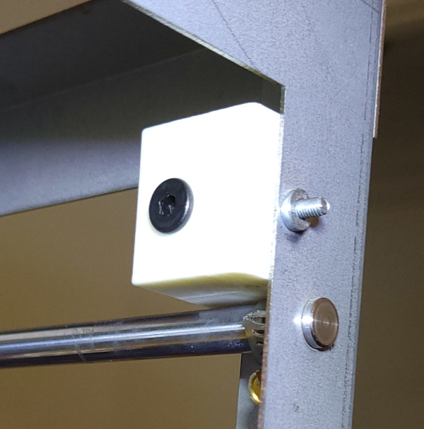
The vertical hole trick didn't work. I can easily pull the line through the hole, but the pulley is too big to hook the line from the front. I'll have to go with wrapping the line around the pulley before I install it in the bracket.
Measurement showed that the new bracket sticks into the solidoodle slightly more than 9mm less than the old bracket. Plus only the very flat bolt head sticks out rather than the end of the bolt plus a nylock nut. Unfortunately, the thing that now collides is the new part cooler air duct:
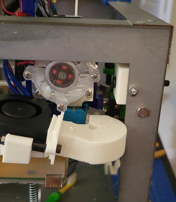
I guess I should put part cooler redesign on my todo list :-).
I got the left bracket printed, and it worked fine as a mirror of the right. I also installed M3 lock nuts on the ends of the mounting bolts that stick out in front. On the sides, I printed some special "washers" to apply force to the frame rather than the bracket and added M5 lock nuts to them, so the brackets are now fully installed.
I also invented a technique for running the fishing line through the idler. I use blue tape with the line stuck to a strip and then the strip stuck to the pulley using a coffee stirrer to reach into it. I can then rotate it around and grab it with tweezers when it comes out the bottom.
The new lines are installed, and shoving it around seems to work, so the hard part is done:
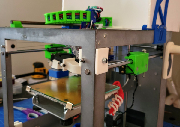
Now I just need to see if I need to cut new holes in the foamboard sides to fit over the new stuff sticking out of the printer (one of the advantages of foamboard as a case material :-).
A little bit off the sides where the new M5 lock nuts sit on the outside, and the case fits as well as it ever did.
When putting the filament back in, I just cranked up the hot end and extruded the leftover bit of filament, while pushing the new filament in after it. The gear eventually grabbed the new filament, and all is back to normal now.
I guess this project is done now. Probably no sense in telling cura (or the firmware) about the new bed geometry till I get a new cooling fan duct that doesn't collide with the frame.
Been working on new duct that takes up less horizontal space, but is bigger to allow more air through:
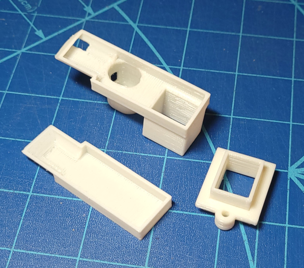
Printed those with supports, now I've super glued them together:
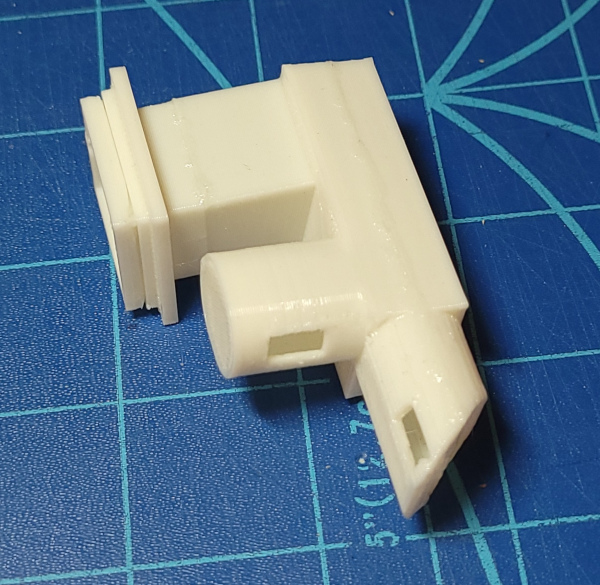
You can see there is lots of horizontal space now, no danger of hitting the frame:
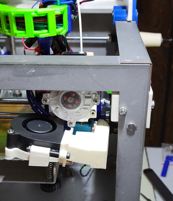
Here's the view from under the nozzle:
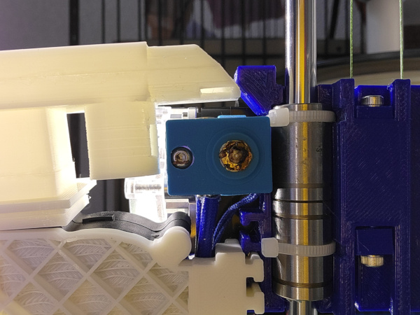
The problem with this new duct is that it is very very low and can run into the swiss clip holding the glass down, so maybe this isn't yet the last duct, since I have so much horizontal space now, I could make it higher and wider and still clear the frame.
Let's go whole hog and get rid of the glass and swiss clips completely. I've ordered a kit to stick a magnetic sheet to the aluminum and use a flexible steel PEI coated plate to print on (though the internet recommends using glue stick on PEI to print flexible filament because it won't come off otherwise).
I've already removed the glass and the kapton tape that was on it when first purchased (came off suprisingly easy for being stuck on so many years).
I should recompute the max bed size now since there are no more obvious ways to increase it. Last time I did this by shoving the carriage as far to one side as I can get, then sending G91 and moving the carriage till it hits the endstop (which conveniently reports the position, thus telling me how far I moved).
As far left as I can go is where the bolt on top of the fan is about to hit the new Y idler bracket. (I runs into other stuff just a couple of millimeters after that, so it isn't worth redesigning the fan mount one more time to lower it). The X endstop is now hit at 134.89.
Doing the same in the Y direction, I get 142.15.
To allow a tiny bit of slop let's call X max 134.75 and Y max 142. That's lots better in Y which was previously 126.87, in X it is a smidge shorter (because I previously couldn't move far enough forward for the bolt on the fan to hit the Y bracket).
I think I can also do a better job of figuring out exactly where the tip of the nozzle can reach on the bed (tomorrow...). I'm thinking blobs of play-doh and raising the build plate into the nozzle to make an impression :-).
The play-doh blobs worked great. I cut a 6 inch square of paper, clipped it to the print bed so it wouldn't shift on me, and squeezed flat some play-doh and put it in 3 corners. I then moved the print head in 20mm from the home positions and raised the bed to get the nozzle to create an impression in the play-doh. Poking a pencil through the play-doh made marks on the paper, then I could remove the play-doh and see where the marks were. In the X direction, the mark is 10.5mm from the right side, so that means when homed, the nozzle is 9.5mm off the right edge. In the Y direction the marks are 21mm from the back edge, so the home position is already 1mm onto the bed.
The actual printable bed area is therefore 125.25 x 142. So I need to tell cura the new bed area and I need to tell the firmware the new X and Y max values.
Go back to my main Solidoodle page.