Bed Heater Upgrade
Everyone who waits for the print bed to heat up eventually starts to think about upgrading the heater :-). This is especially helpful if you switch to some thicker material for the print surface (ceramic, glass, granite, etc).
If you want, you can skip all the waffling that follows and go right to the the decision I made about how to support the new heater.
I have a Solidoodle 2 with the new printrboard electronics and I'm trying to gather useful tidbits in one place so I can decide what to do. An awful lot of terrific information was provided by lawsy's Heated Bed Upgrade thread, but that is for the old electronics, so some tweaking is needed. Things I think I know:
- I can buy a 12V SILICONE RUBBER HEATER BED 150MM X 150MM (6"X6") from QU-BD.
- In theory, the printrboard has beefy enough PBC traces to control a QU-BD heater if enough power is available (see this post by Hazer). But the board connectors are another matter (see below). On the other hand, some folks disagree about the traces on the printrboard (naturally :-).
- Some folks have used a power supply such as this SUPERNIGHT box. Others pick something higher quality and more expensive like Meanwell 12 Volt 350 Watt Ul Switching Power Supply 120 Volt Input Constant Voltage By Ledwholesalers, 3251-12v. I also asked about using these in this forum thread and apparently I do need to run power from all the connectors provided on the supply to avoid exceeding the rating of an individual connector. That thread also leads to the next item in the list:
- The barrel style power connector on the printrboard is almost certainly not rated for the bigger power supply (see, for instance, this data sheet for a similar connector found on digi-key which is rated 8A at 16V). I could either solder wires directly to the printrboard in place of the power jack, or I could decide it is simpler to bypass all the altering of the printrboard and drive the heater off a separate solid state relay controlled by the printrboard. (This Crydom SSR from digi-key looks good, but also needs a heat sink and thermal pad.)
- This all, naturally, leads to the question of the heater connector on the printrboard. No doubt it is also not rated high enough to run the QU-BD, so I suspect we are talking replacing that as well (or, once again, using an SSR). The SSR route is looking more and more attractive :-), but replacing the connectors is a lot cheaper.
- Connectors that are rated for high current are maybe not hard to find, but are confusing to find. I also don't know what the hole spacing is on the printrboard for the power and bed heater connections, so I'd have to find that out before I could tell what connector to get. I have determined that the category I want on digi-key is probably Connectors, Interconnects > Terminal Blocks - Wire to Board... Yikes! I've just downloaded the solidoodle printrboard eagle files. The power connector is hopeless to match. The ground is a slot shaped thing and the power is a big pin that sticks out the back of the connector. I'd pretty much have to just solder in wires which might need to go some place like a nearby terminal strip (perhaps something like this one). That is looking as messy and inconvenient as a solid state relay.
- If I go for the SSR, this heat sink is in stock and looks beefier than the recommended heat sink crydom's selector tool came up with (which isn't in stock). I'll also need a adhesive thermal pad. I don't think I'll need either of the lug terminals they have in the catalog - they seem to be for much bigger wire than I'll be using.
- The QU-BD bed is not flat. It has lumpy parts in the middle for the wires and thermistor. I'll need something to support the heater between the aluminum and the glass to allow for the lumps. One such solution is Solidoodle Silicone Bed Mounting Kit. I suppose I could also carve out space in a piece of wood or MDF, but that might warp over time. Another thought I've had is to use something like wallboard compound or dental stone to cast a conforming surface for it to sit on. Perhaps I could even embed some small threaded rod in the casting to provide a way to clamp it and the glass to the existing aluminum bed.
- Having replaced the heater, and hooked up the QU-BD thermistor in place of the one in the original heater, I'll then need to fiddle the firmware. Not only does it need to know about the new thermistor, I'll also need to run the heatbed PID calibration and update the parameters in the firmware (probably a two step process - first update the thermistor info, then run the calibration and update again with the new PID parameters).
- To add to the confusion, there is a totally different option as well: Completely replace the electronics with a RAMPS 1.4 setup such as SainSmart Mega2560 + A4988 + RAMPS 1.4 3D Printer KIT For Arduino RepRap. I think that prebuilt kit comes with beefy enough connectors and mosfets to handle the QU-BD directly, and probably isn't much more expensive than adding the SSR. (But wandering over to the wiki entry for the RAMPS board talks about 11A for the heater, and the QU-BD says it takes 11.5A, so it is right on the edge).
Perhaps I should call this Project Snowball as the implications of changing the heater do seem to be snowballing here...
Anyway, I think I've discovered 3 main options (so far):
Modify Printrboard
Desolder the power and heatbed connectors. Solder in some heavy duty wires in place of connectors and run it to terminal blocks (I can probably mount the terminal blocks on my electronics cover or print a new cover with additional places for the terminal blocks to go). Probably should add jumpers to the MOSFET as well to augment traces on the printrboard just in case they aren't adequate.
Pros: Cheapest option. As long as I have the board out, I can also solder in all the missing headers for possible future use.
Cons: Most likely option to destroy the printrboard. Extra wires and terminal block are a bit messy.
Solid State Relay
Drive a SSR from the printrboard heater output and use the separate power supply and SSR just for the heater.
Pros: Simplest to wire up.
Cons: Good quality SSR and heatsink is more expense. Even bigger wiring mess than above.
Switch to new motherboard
Buy one of the RAMPS 1.4 kits (prebuilt is much simpler) and rewire everything, including wiring in the new bed heater.
Pros: Lots of features available on RAMPS for future hacks.
Cons: Most expensive option. Big pain to rewire everything. Not entirely certain RAMPS is hefty enough to drive QU-BD heater. (But a RAMBo is clearly beefy enough, so perhaps that would be the motherboard to use if switching motherboards.)
I think I've decided to go with the Modify Printrboard option (perhaps after some practice desoldering things :-). I've decided to use EC3 connectors inline on the high power cables and solder the cable ends to the printrboard in place of the existing connectors. I also ordered this power supply
Haven't touched the printrboard yet, but I have started work on other cables:
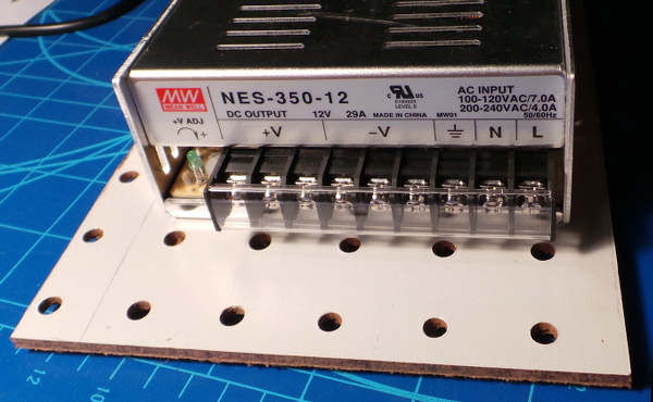
The above pic shows the 3 12V output and 1 115V input on the power supply and the perfboard I have it mounted on with 4 M4 10mm bolts. The perfboard will, in turn, be mounted to the wire shelf the solidoodle is sitting on.
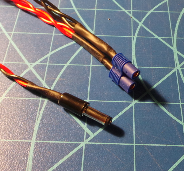
The power cables to attach to the power supply. I have 3 18 gauge wire pairs going into the EC3 connector, and 1 18 gauge wire pair going into the DC plug that will provide extra fan power. The most difficult part was shoving the sockets into the EC3 shell after soldering the wires into them. The EC3 connector will eventually mate with a matching male connector when I figure out where to solder the wires to the printrboard. I got the three wires in by stripping the ends, twisting them together, tinning them, then clipping the end square (tinning first is important, otherwise a million little clipped wires fly everywhere).
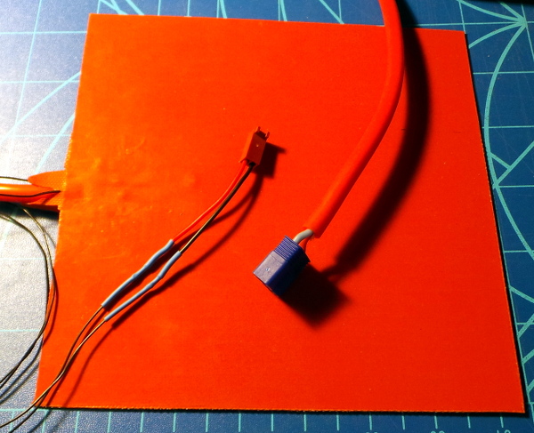
Here I have a 2 wire fan connector I salvaged from an old dead computer fan spliced to the QU-BD thermistor wires (I checked first that the connector fit on the printrboard). I also have a male EC3 connector soldered to the heater power. Again, I'll be modifying the printrboard to solder on wires with a female EC3 connector to hook up the heat pad. (I forgot to check first, but fortunately it turns out the connector is small enough to fit through the holes in the back of the printer :-).
I've now got the power supply mounted to the wire shelf where the printer sits. Here's the back showing the extra piece of perfboard used to clamp it to the shelf edge with a couple of 1/4-20 bolts:
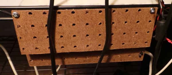
And here is the business end with all the wires screwed into the terminal strip, anchored with some wire tires for strain relief, and the plastic shield clipped over the terminal strip for safety:
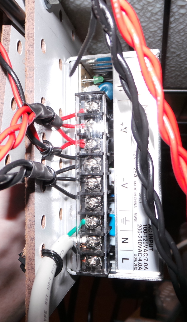
(Getting all the wires connected solidly with my fat fingers in the little gaps between the plastic separators wasn't easy :-).
Next up is the tricky part: Figuring out where to wire in some extra connections on the board for power in and bed heater out. I can look at the eagle files to get some ideas, but I'm definitely going to need to take the board out and poke around to find good places to add the wires. I may need to desolder the connectors for power and bed heater, or I may just add new wires and leave the old connectors un-used. I'll see what I can figure out when I examine the board more closely. Scraping away laquer may be involved as well.
At the moment I'm leaning toward 3 ground wires going to the existing power connector ground, and the two hotbed and extruder mosfet grounds. Then for the three +12V wires, have one going to the existing power connector, and two going directly to the new EC3 hotbed output connector. Then I just need two ground outputs from the hotbed mosfet to make the other half of the hotbed EC3 output. I think that will direct power where it is needed, and might be reasonably simple to solder (but I'll have to look).
I plan to replace the connector on the end of the existing bed heater wires with the EC3 style connector so I can test that things work with it before I swap in the QU-BD heater.
As long as I have the board out, I also plan to suck the solder out of all the un-used header holes and solder in all the missing headers so I'll be able to add things like a PWM controlled fan, out of filament sensor, etc.
I have the board out now (after taking lots of pictures so I can be sure to get everything hooked back up the way it was), and I've hit my first obstacle. I've been sucking the solder out of the holes for all the missing headers, and three of the holes appear to be obstructed (even though the eagle files indicate they should be the exact same kind of hole as all the others):
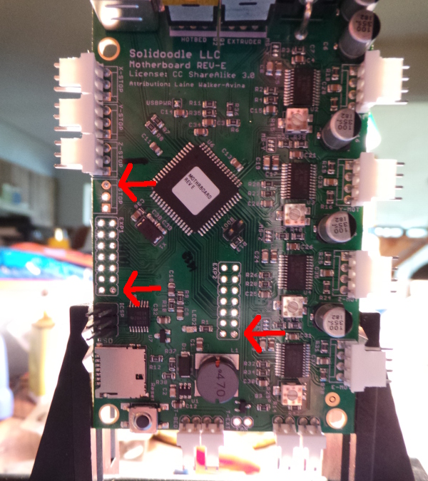
I've tried heating a copper wire to see if I can poke it through, and nothing happens. It is like they aren't really drilled through.
Nope, turns out that they are just really hard to heat up. Being connected to the ground plane (or maybe power plane, not sure which) puts them in contact with lots of heat conducting copper. I got one more cleared by cranking the heat way up on the iron, but the last two are too stubborn even for that. I guess I'm going to need some tiny drill bits...
OK, I eventually managed to get all 3 holes cleared. The last one I added a bunch of solder and finally got the new blob heated up and sucked out. Maybe it was lower melting point than what the wave solder machine used. Maybe it was just enough extra mass to retain more heat. Anyway, I finally have all the missing headers soldered in:
It was really difficult to insert the headers in the holes with tiny bits of leftover solder in them. I used a technique that probably isn't recommended - I reamed them out a little bit with one of the same sized pins held in a pair of needle nose pliers, together with gradually working the pins into the holes, I eventually got the headers inserted all the way. Unfortunately, I killed the whole day doing that, so I guess I'll figure out how to add extra power another day. I think I'll hook it back up for now and see if it still works...
...And amazingly, it is working after getting it all hooked back up. I printed a small part and everything functioned correctly. The one new header I can easily test is the PWM fan, and if I hook a fan up to it and play with the manual controls, it does seem to work as expected. I guess I didn't destroy anything yet :-).
Having thought about how to get the extra power hooked up for a while now, and having seen how hard it is to desolder things connected to the big old power and ground planes, I think I'll leave the current power connector alone. Instead of trying to desolder it, I'll cut the leads on the existing 12V power supply so I can use the existing power plug for about 1/3 of the juice. I can then run extra 12V power cables directly to one of the connections to the new heatbed and I can solder extra ground lines directly to the source pins on the two MOSFETs (bed and extruder heaters). I can then remove the existing connector for the bed heater and solder wires to the switched ground MOSFET outputs available where the connector was. Hook up the appropriate EC3 connectors to the ends of the wires, and I can plug and unplug everything with relative ease. At least that is the plan today.
Meanwhile, I've started on the custom creation I'll need to allow the QU-BD heater pad to sit flat given all the lumpyness on the bottom. I've constructed this form:
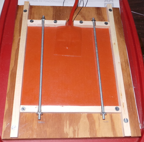
The plan is to build up some wallboard compound (not because it was a carefully researched ingredient, but merely because I have some :-) to fill the form and encase the 8-32 threaded rods. Once it is fully hardened, and the surface sanded flat, I can extract it from the form, turn it over and place it on the printbed, thus giving me the full sized flat surface of the QU-BD pad to heat the glass. This also gives me some 8-32 rods sticking out of either end to use to secure the bed and the glass.
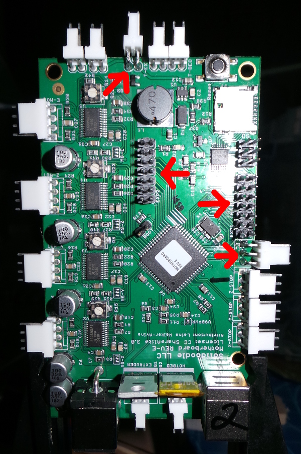
But before I install a new heat bed, I want to make sure all the circuit board mods work. I've been studying them very carefully to make sure I don't screw anything up. The tricky bits are the additional wires to the mosfets (might as well wire up the hotend mosfet as well as the heat bed as long as I'm screwing with this). The input to each mosfet is the ground. I'll want to solder additional ground wires directly to the bottom pin of the mosfets as they appear in bright green on this diagram:
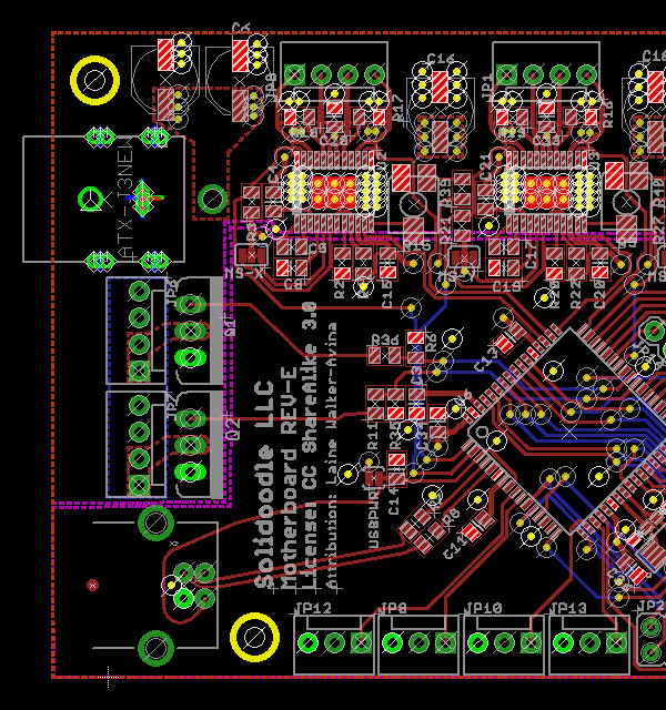
The switched ground output from each mosfet is the center pin which is directly connected to the bottom two pins of the existing molex connectors highlighted here:

I'll need new wires from some combination of those pins soldered on the circuit board to connect to the ground of the hot end and heat bed.
If I successfully get past those tricky bits, the rest is easy:
- Cut the existing barrel connector off the stock solidoodle power supply (or find a new one somewhere, but I'm not going to need the old power supply, so it is simplest to cut it).
- Cut the existing connectors off the hot end and heat bed power lines and solder on new male EC3 connectors.
- Prepare a new male EC3 connector that will plug into the female EC3 already attached to the new power supply. This connector will need three wires from each side.
- One set of wires will connect to the barrel connector which was removed from the old power supply.
- Two sets of ground wires will be the wires soldered to the bottom pins of the mosfets.
- Two sets of 12V wires will go directly to the 12V side of the female EC3 connectors that will pair up with the hot end and heat bed.
- Finally, the two wires from the middle mosfet connection will go to the ground side of the female EC3 connectors for the hot end and heat bed.
If I'm not careful that will all be a bit of a rats nest (and it will be really important to properly label which connector goes where :-), but at least I'll have lots of power now for the heat bed upgrade (and maybe to install a new hot end someday as well).
At this point I'll want to put everything back together and make sure the existing heat bed is working properly with the new wiring. If all is well, substituting the new heat bed should be fairly simple.
Go back to my main Solidoodle page.