My Gauge Mount
Let's begin at the end with the final results:
All the openscad and .stl file are collected in newmount.tar.bz2.
The new and improved main openscad file looks like:
// New Dial Indicator mount for the somewhat weird extruder assembly
// on my solidoodle.
//
// My extruder definitely appears to be different that some of the other
// ones folks have made mounts for. I have acrylic all the way around my hot
// end where it goes through the wood piece and I have 4-40 bolts in
// "backwards" from earlier extruders.

// Global parameters

// The width of the extruder jigsaw acrylic I'm going to be sitting on.
// Also the width of most of the parts of this dial mount.
//
mountwidth = 50;

// The amount to "explode" the parts by in the exploded view.
//
explode = 3;


// ******************************************************************* top plate
//
// Part 1: "tp" - top plate. The mounting plate to go above the wood piece
// on my extruder. Need 1 of these.
//
// This plate goes above the wood piece and fit on my extruder so it can be
// screwed onto the bits of 4-40 bolts that stick out on the bottom two
// bolts that go through the jigsaw.

// The width of the acrylic to the right side of the left bottom screw
//
tpright = 8.5;

// The width of the acrylic to the left side of the right bottom screw.
//
tpleft = 11.3;

// The diameter of the plate openings for the 4-40 screws and nuts.
//
tpholedia = 8;

// The height of the plate as it sits on the wood.
//
tpheight = 10.3;

// tpmiddle is the depth (from front of wood to front of acrylic) of the
// acrylic around the top of the hotend in the middle of the top plate.
//
tpmiddle = 3;

// tpside is the depth of the acrylic on each side of the plate (the side
// acrylic is set back farther than the middle).
//
tpside = 4.4;

module topplate() {
   difference() {
      union() {
         cube([mountwidth,tpheight,tpmiddle]);
         cube([tpright+(tpholedia/2),tpheight,tpside]);
         translate([(mountwidth-tpleft)-(tpholedia/2),0,0])
            cube([tpleft+(tpholedia/2),tpheight,tpside]);
      }
      translate([tpright+(tpholedia/2),(tpholedia/2),0])
         cylinder(h=(tpside+1),r=(tpholedia/2));
      translate([mountwidth-(tpleft+(tpholedia/2)),(tpholedia/2),0])
         cylinder(h=(tpside+1),r=(tpholedia/2));
      translate([tpright+(tpholedia/4),0,0])
         cube([tpholedia-(tpholedia/4),(tpholedia/2),(tpside+1)]);
      translate([mountwidth-(tpleft+tpholedia),0,0])
         cube([tpholedia-(tpholedia/4),(tpholedia/2),(tpside+1)]);
   }
}


// ********************************************************************* hex nut
//
// Part 2: "hn" - hex nut. The small cylinders to hold the 4-40 hex nuts
// that screw on the ends of the bolts sticking out of the extruder (and hold
// the whole thing on). Need 2 of these.

// Measure width of 4-40 nut flat side to flat side (and add any slop
// you think you might need to be able to fit the nut in the printed part).
//
hnwidth = 6.5;

// Measure thickness of the 4-40 nut.
//
hnthick = 2.5;

// hndia is the diameter of the cylinder that holds the nut.
//
hndia = 10;

// hntop is the thickness of the top layer of plastic "above" the nut.
//
hntop = 2;

// hncylthick is the thickness of the trap cylinder
//
hncylthick = hntop+hnthick;

// hnhole is the diameter of the small center hole
//
hnhole = 3;

module hncutout() {
   intersection() {
      translate([-hnwidth,-(hnwidth/2),0])
         cube([hnwidth*2,hnwidth,hnthick]);

      rotate([0,0,60])
         translate([-hnwidth,-(hnwidth/2),0])
            cube([hnwidth*2,hnwidth,hnthick]);

      rotate([0,0,120])
         translate([-hnwidth,-(hnwidth/2),0])
            cube([hnwidth*2,hnwidth,hnthick]);
   }
}

module hexnut() {
   difference() {
      translate([0,0,-hntop]) cylinder(r=(hndia/2), h=hncylthick);
      hncutout();
      translate([0,0,-(hntop+1)]) cylinder(r=(hnhole/2),h=(hntop+1));
   }
}

// ****************************************************************** nut handle
//
// Part 3: "nh" - nut handle. Glued to the hexnut piece to provide a handle
// to use when screwing the nut on the bolt end. Need 2 of these.

// height (or length depending on direction you are looking) of handle.
//
nhheight = 8;

// diameter of handle.
//
nhdia = 6;

// Tiny cone shaped "nub" on end of handle fits the hole in the hexnut piece
// for easy centering when gluing in place.
//
nhnubdia1 = hnhole-0.2;
nhnubdia2 = 2;
nhnubheight = 2;

module handle() {
   union() {
      cylinder(r=(nhdia/2),h=nhheight);
      translate([0,0,nhheight-0.1])
         cylinder(r1=(nhnubdia1/2),r2=(nhnubdia2/2),height=nhnubheight);
   }
}

// **************************************************************** bottom plate
//
// Part 4: "bp" - bottom plate. Glues onto the top plate to wrap around the
// wood piece and provide part of the holes where the hexnuts will be
// trapped as well as some stubs where the piece with the hole the dial
// indicator goes in can be glued. Need 1 of these.

// The thickness of the wood piece plus a little slop.
//
bpwood = 5.05;

// The vertical thickness of the lip that goes under the wood.
//
bpvertlip = 3;

// The depth of the lip on each side (more room under the wood on the
// sides than in the middle).
//
bpside = 7;

// The depth of the lip in the center (where these is less room and we
// don't want to jam into the extruder).
//
bpcenter = 3;

// The thickness of the bottom plate.
//
bpthick = 4;

// The diameter of the trap holes the hexnuts will fit in.
//
bptrapdia = hndia+2;

// The size of the "nubs" for guiding the gluing of the guage hole.
//
bpnubsize = 5;

// The distance the nubs should be from the edges of the plate.
//
bpnuboff = 3;

module bpstruct() {
   union() {
      cube([mountwidth,bpthick,tpheight+bpwood+bpvertlip]);
      cube([tpleft,bpthick+bpside,bpvertlip]);
      translate([mountwidth-tpright,0,0])
         cube([tpright,bpthick+bpside,bpvertlip]);
      cube([mountwidth,bpthick+bpcenter,bpvertlip]);
      translate([bpnuboff,-(bpnubsize-1),0])
         cube([bpnubsize,bpnubsize,bpnubsize]);
      translate([mountwidth-(bpnuboff+bpnubsize),-(bpnubsize-1),0])
         cube([bpnubsize,bpnubsize,bpnubsize]);
   }
}

module bphole() {
   translate([0,bpthick+1,bpwood+bpvertlip+(tpholedia/2)])
      rotate([90,0,0])
         union() {
            cylinder(h=bpthick+1,r=(bptrapdia/2));
            translate([-(bptrapdia/2),0,0])
               cube([bptrapdia,tpheight,bpthick+2]);
         }
}

module bottomplate() {
   difference() {
      bpstruct();
      translate([tpleft+(tpholedia/2),0,0])
         bphole();
      translate([mountwidth-(tpright+(tpholedia/2)),0,0])
         bphole();
   }
}

// ******************************************************************** nut trap
//
// Part 5: "nt" - nut trap. The remaining bits of the trap for the hexnut
// pieces, glues onto the bottomplate with the handles sticking through the
// homes. Need 2 of these.

// Inner diameter of cylinder that traps the nuts.
//
ntinnerdia = bptrapdia;

// Outer diameter of same.
//
ntouterdia = ntinnerdia+2;

// Space required for screws to travel while being screwed or unscrewed
//
ntinnerheight = 2;

// Outer height of the nut trap.
//
ntouterheight = ntinnerheight + 1;

module nuttrap() {
   difference() {
      union() {
         cylinder(r=(ntouterdia/2), h=ntouterheight);
         translate([-((ntinnerdia-1)/2),0,0])
            cube([ntinnerdia-1,(tpheight-(tpholedia/2))+1,ntouterheight+2]);
         translate([-((ntouterdia+4)/2),tpheight-(tpholedia/2),0])
            cube([ntouterdia+4,2,ntouterheight+2]);
      }
      translate([0,0,ntouterheight-ntinnerheight])
         cylinder(r=(ntinnerdia/2), h=ntinnerheight+2);
      translate([0,0,-1])
         cylinder(r=((nhdia+2)/2),h=ntouterheight+2);
   }
}

// ****************************************************************** guage hole
//
// Part 6: "gh" - guage hole. The part that glues on the very bottom and
// has the mounting hole for the dial indicator.

// The amount of clearance I need between the mounting hole and the rest
// of the mount (make sure the back of the guage is clear of the handles on
// the hexnuts).
//
ghclear = 10;

// The outer diameter around the hole that hols the dial guage.
//
ghouterdia = 20;

// How long is the hole the guage runs through.
//
ghthick = 15;

// Inner diameter of the hole. Needs to have a little slop to make sure the
// guage will fit in the printed part.
//
ghinnerdia = 10.33;

// How thick is the back of the plate.
//
ghback = 7;

// How wide is the notch in the back of the plate.
//
ghnotchw = 3;

// How high is the notch in the back of the plate.
//
ghnotchh = 4;

// How big a diameter hole to use for cutout in the back that make room for
// the extruder nozzle to fit.
//
ghnozdia = 40;

// How far into the back should the nozzle hole sink?
//
ghnozsink = ghnotchw;

// How far from the side of the back plate should the nozzle cutout be centered?
//
ghnozcen = 23;

// How far up should the nozzle cutout go?
//
ghnozhigh = ghthick+ghnotchw - (ghnotchh + 1);

module ghbackhole() {
   union() {
      difference() {
         cube([mountwidth,ghback,ghthick+ghnotchw]);
         translate([0,ghnotchh,(ghthick+ghnotchw)-ghnotchh])
            cube([mountwidth,bpnubsize,bpnubsize]);
         translate([bpnuboff-0.1,0,(ghthick+ghnotchw)-ghnotchh])
            cube([bpnubsize+0.2,bpnubsize,bpnubsize]);
         translate([mountwidth-(bpnuboff+bpnubsize+0.1),
                   0,(ghthick+ghnotchw)-ghnotchh])
            cube([bpnubsize+0.2,bpnubsize,bpnubsize]);
         translate([ghnozcen,((ghnozdia/2)+ghback)-ghnozsink,0])
            cylinder(r=(ghnozdia/2),h=ghnozhigh);
      }
      translate([0,ghback-0.01,ghnozhigh+0.01])
         rotate([-90,0,0])
            rotate([0,90,0])
               linear_extrude(height=mountwidth)
                  polygon(points=[[0,0], [ghnotchw,ghnotchw], [ghnotchw, 0]]);
   }
}

module mountinghole() {
   difference() {
      union() {
         cylinder(h=ghthick,r=(ghouterdia/2));
         translate([-(ghouterdia/2),0,0])
            cube([ghouterdia,1+ghclear+(ghinnerdia/2),ghthick]);
         translate([-(mountwidth/2),ghclear+(ghinnerdia/2),0])
            ghbackhole();
      }
      cylinder(h=ghthick,r=(ghinnerdia/2));
   }
}

// *************************************************************** exploded view
//
// Don't print this, just look at it :-).

module exploded_view() {
   union() {
      rotate([90,0,0])
         union() {
            topplate();
            translate([tpright+(tpholedia/2),(tpholedia/2),-(hnthick+explode)])
               hexnut();
            translate([mountwidth-(tpleft+(tpholedia/2)),
                       (tpholedia/2),-(hnthick+explode)])
               hexnut();
            translate([tpright+(tpholedia/2),
                       (tpholedia/2),-(hnthick+nhheight+3*explode)])
               handle();
            translate([mountwidth-(tpleft+(tpholedia/2)),
                       (tpholedia/2),-(hnthick+nhheight+3*explode)])
               handle();
            translate([tpright+(tpholedia/2),
                       (tpholedia/2),-(hnthick+nhheight+5*explode)])
               nuttrap();
            translate([mountwidth-(tpleft+(tpholedia/2)),
                       (tpholedia/2),-(hnthick+nhheight+5*explode)])
               nuttrap();
         }
      translate([mountwidth,bpthick+explode,-(bpwood+bpvertlip)])
         rotate([0,0,180]) bottomplate();
      translate([mountwidth/2,
                 (ghinnerdia/2)+ghclear+explode+bpthick+(ghback-ghnotchw),
                 -(bpwood+bpvertlip+ghthick+ghnotchw+explode)])
         rotate([0,0,180]) mountinghole();
   }
}
This defines all the variables and modules, but doesn't actually create anything. All the other scad files for the individual parts simply include this and create the appropriate module.
And I even incorporated an exploded view for fun:
include <newmount.scad>;

exploded_view();


Now to go back through the history:
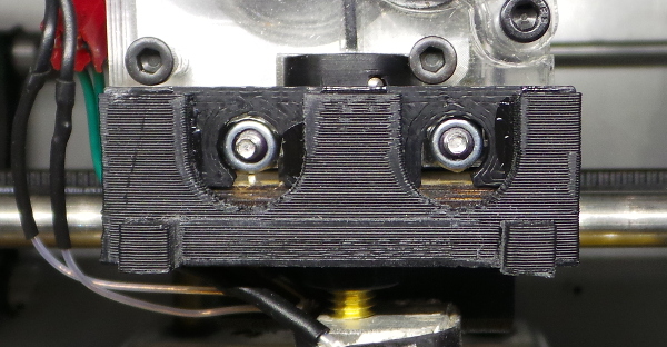
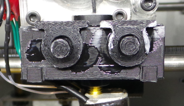
The Dial Indicator Mount for Solidoodle 2 on thingiverse was clearly designed for a different Solidoodle 2 extruder assembly than the one I have. The major things that interfere with using that mount are shown here:
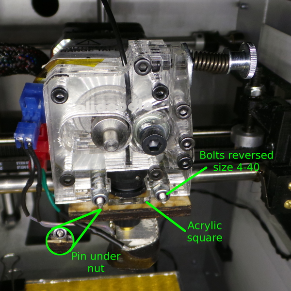
The sensible thing to do would probably be to just modify the original mount a bit, cutting out places for the acrylic square and pin to fit then just use two magnets to mount it on the top nuts, but designing absurdly complicated things in openscad has gotten to be fun, so I'm building a brand new mount from scratch.
By picking off pixel counts in close-up shots of the assembly and comparing threads per pixel and wot-not to known M3 bolts, I decided the reversed bolts on my extruder were 4-40 (weird, I know with everything else metric), and was able to get some 4-40 nuts (Broward Bolt, just up the street from where I work is a wonderful place that stocks everything in bolts and nuts and is willing to sell small or large numbers to anyone).
The 4-40 nuts did indeed fit the ends of the bolts as smooth as silk. No rattling and no binding, so that is pretty much proof positive they are 4-40.
Anyway, given that, my plan became to make a dial indicator mount that could be secured by screwing it on to the ends of the 4-40 bolts.
I designed a plate that fit around all the pins and nuts and acrylic square:
include <newmount.scad>;

topplate();
I then added some little cylinders I could fit the 4-40 nuts in to screw down the plate:
include <newmount.scad>;

hexnut();
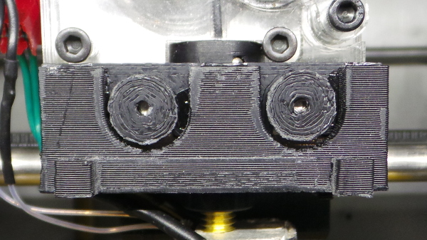
I dabbed a little J-B Weld into the nut opening with a toothpick, then pressed the nuts in place with the end of a pen. After the epoxy sets, nothing should get the nuts out of the cylinder.
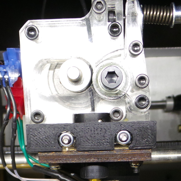
Here is how it mounts on the extruder (with early versions of the nuts missing the center hole):
Now, because small parts like the nuts can get easily lost, it is time to design the holder for the dial gauge that can be glued to the plate and also trap the nuts in place so they can't get separated. Obviously, if I do that, I'll need handles to glue on the back of the disks that can escape the trap so I can screw the nuts on. Also, it is worth noting that the main criteria for the gauge holder is that the pointy end winds up below the end of the extruder (otherwise it is hard to measure anything with it :-).
include <newmount.scad>;

bottomplate();
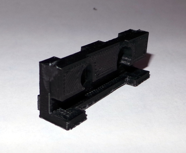
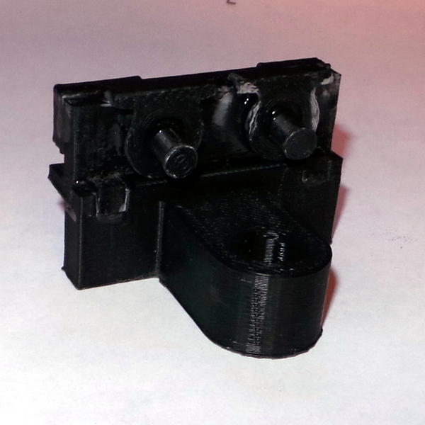
I've now glued the mount to the plate, and you can see how it fits on the extruder:
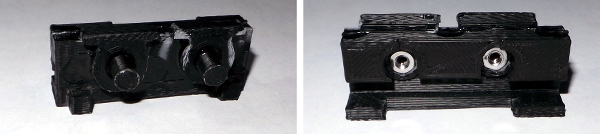
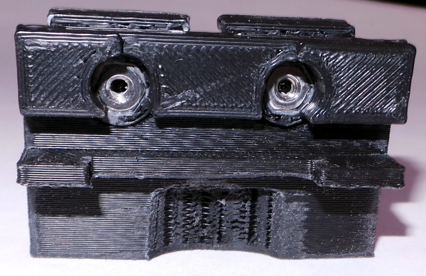
All the complicated geometry is on the reverse:
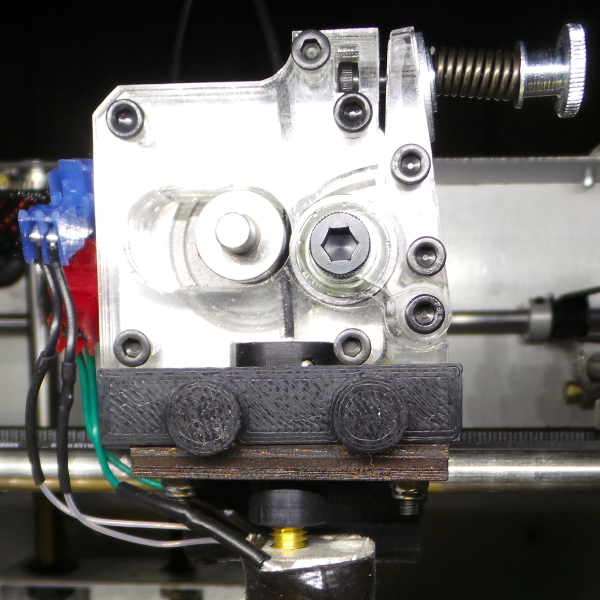
And with the nuts screwed on:
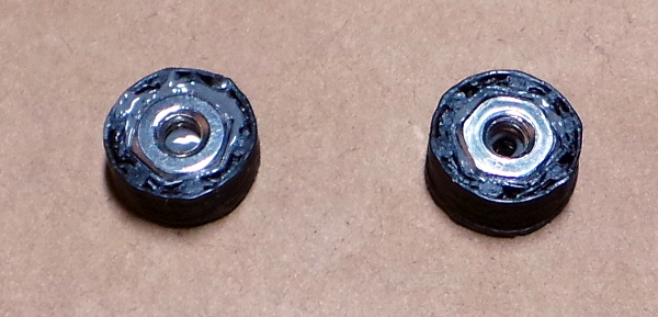
Measuring the unscrewed nuts shows that I need the cage to give the nuts a couple of millimeters clearance to unscrew all the way:
include <newmount.scad>;

nuttrap();
And I'll need handles to glue on the nuts to stick out of the cage:
include <newmount.scad>;

handle();
Put them all together (being very careful not to glue the handle or nut to anything when gluing on the cages) and you get:
Now I need one last piece to glue on, the one that provides the hole for the dial indicator to sit in. Checking the dial gauge I have I see the plunger is so long, there is no way I'm likely to mount it too high, but I do need to make sure the mounting hole is far enough in front of the rest of the mount to allow the back of the gauge to clear the handles I use to screw in the nuts.
include <newmount.scad>;

mountinghole();
NOTE: This version of the final piece has had the hole moved closer to the extruder since there was more clearance than I thought for the gauge to fit, and the model now has the cutout on the back to avoid hitting the extruder nozzle. I haven't printed one to test though, but it looks right to me :-) All the photos reflect the old model before these fixes..
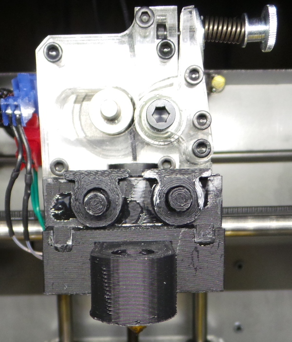
Printed and glued on:
Wups! I thought I remembered taking into account the actual print head at the bottom of the extruder. It sticks out a bit with the wires and tape and wot-not. Apparently I forgot about it, so I had to take a chunk out of the bottom the old fashioned way with a little rotary sander and a dremel tool:
Now it finally fits on the extruder assembly:
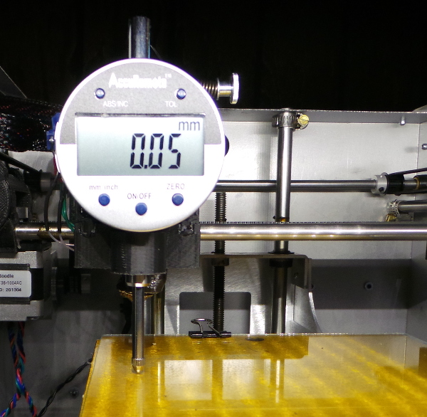
And it even works (and boy, is my bed in need of leveling :-).
So the next task is obviously to do something about making it easier to turn the leveling screws from the wrong end. I'll probably start by practicing cutting slots in the ends of some sample sacrificial screws with the dremel tool to see if I think I can do the same to the real screws (seems like the simplest technique of all the ones I read about on the forums).
I was wrong: My practice clearly showed I don't have the steady hand required to cut the slots. I'm going with this thumb screw instead.
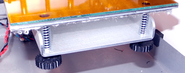
I got the screws to cut threads pretty easily by brushing on a bit of acetone before screwing the thumbscrew into place, but I didn't have very much spare screw thread to work with, so I couldn't get the thumbscrews to stay on without glue. I used a tiny dab of J-B Weld in each screw hole and let them cure overnight before trying to do any adjustment. They are by golly permanently attached now. No more unscrewing off the thread instead of turning the adjustment screw.
Now the problem is that the silly mount described here doesn't really hold the dial indicator firmly enough. It is OK going back and forth across the printbed, but going in and out rocks the mount and gives wildly random results. So it is indeed time to take the sensible approach and go with the tweaking of the original mount and using magnets.
Even with the rocking mount, I was able to get the bed more level than it had been, so I proceeded to follow the instructions from here and here to try and get things printing accurately according to the dimensions in the models I start from. I also measured the thickness of the skirts and brims I printed while doing the calibration tests to try and dial in the z-stop setting exactly, and finally got the first layer to come out to almost exactly 0.3mm. The result (eventually) was this near perfect calibrarion print:
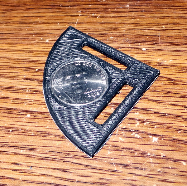
I did have to file down a few irregular spots in the circle to get the nickel to fit, but the slots worked perfectly with the nickel just barely touching the sides while sliding through. It may not be perfect yet, but it is a heck of a lot better than it was when I started.
Hopefully this means I can measure the positions of the new obstructions on my extruder and modify the model of the magnetic mount to get it to fit right the first time.
Nope. Tried it, still can't get it to fit. I may have to print some thinner test pieces to dial in the correct hole positions and essentially build a similar magnetic mount from scratch.
Meanwhile, I don't think I'm really calibrated correctly yet as I tried to print the Solidoodle Extended Filament Guide and no power on earth can get the thing to snap onto the shafts, so it is really printing a tad too far apart on the X axis, but the print itself came out rather nice:
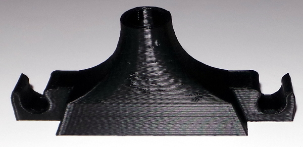
Analyzing the part in netfabb, I see the X size is 96.96 and the actual printed object came out as 98.10, so I need to fiddle the X calibration again. The Y size of the model is 20 and the measured size is 20.08. Unfortunately that X size makes no sense with the model bigger than the actual part since the actual part is already too big to fit on the shafts, so I guess my X calibration may be off, but it has nothing to do with the problem I'm seeing with the guide fitting on the solidoodle. Sigh...
Go back to my main Solidoodle page.