Extruder Flow Calibration
As part of the ongoing attempts to perfect the calibration of my solidoodle, I made a copy of seaton's Extruder Calibration Tool V2. I needed a little filing to get the top slider to fit over the base and move freely, and to get the filament to be able to snap into the top, but once I got that done, it seemed to work fine.
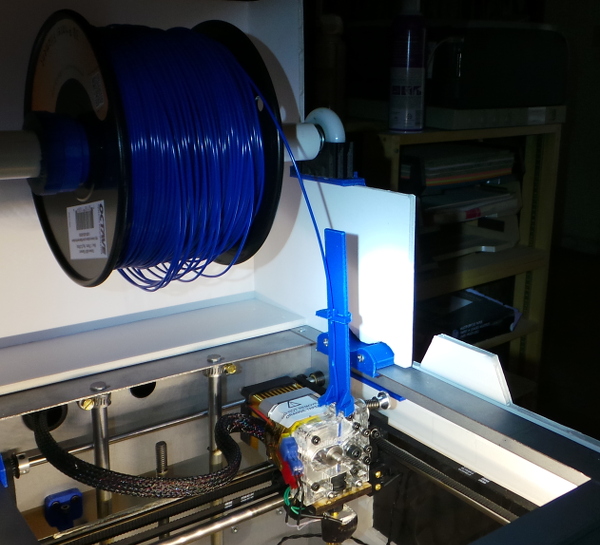
On my first use, I heated up the extruder, attached the gadget to the filament and extruded 10mm just to make sure everything was primed and ready, then I measured down from the top of the top post to the top of the slider using my calipers, and extruded 10mm 3 more times, measuring each time:
| Start | 13.02 |
| +10 | 23.23 |
| +20 | 34.08 |
| +30 | 45.24 |
That says I'm extruding 10.74mm when I think I'm extruding 10mm, so I multiply the steps per mm value for extruder in the firmware eprom settings by 10/10.74 and update the eprom.
I then tried again, just measuring start (23.32) and end (51.87) after hitting extrude 10mm 3 times. Now it is telling me I am under the mark and I need to bump the value back up by (30/28.55).
One more measurement of just 10mm extrusion gives me 62.08 to 72.67 which is back to being tad over 10, but is probably as close as I'm going to get.
Now I need to set the flow rate.
Following the instructions in there, I print this rather nice looking box:
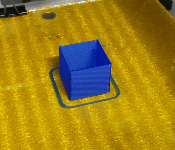
And just like the blog entry above, I also get 0.51 as the wall thickness, so I also want an extrusion multiplier of 0.82.
Printing again with the new multiplier, gives a box that looks very similar:
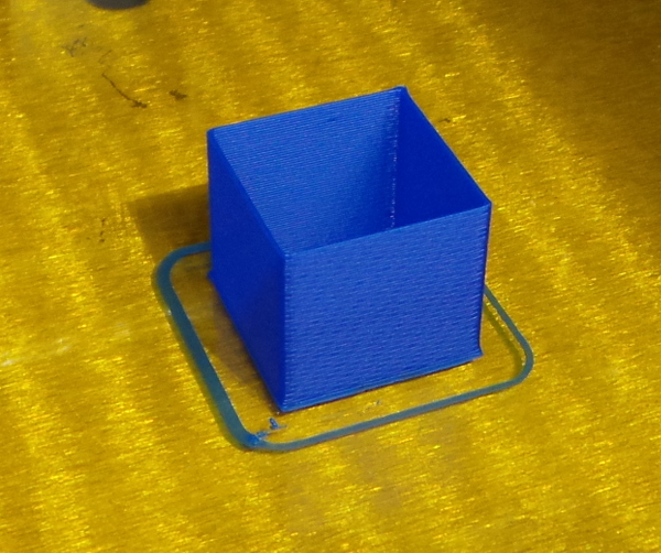
However, I get either 0.42 or 0.43 for the wall thickness when I measure it now, which is pretty darn perfect.
The first layers is, however squashed a bit. Let's print a cube that is just 0.3mm high (the presumed first layer thickness) and measure how thick it really is.
Hmmm... The x-y back and forth printing seems to wind up generating a thicker layer that doesn't really represent the thickness very well.
Let's try it again with a brim (which is laid down in a nice smooth continuous layer) and see how thick it is.
That doesn't really work much better, but you can certainly see differences between different test prints when moving the z-stop setting, so I just fiddled with it till is sorta "looked good" (I wish I could come up with something less subjective :-).
Anyway, the first layer on the test cube doesn't look as squashed out now, so I think I have things dialed in pretty well.
I'm still suspicious of the bed level and flatness though. I may need thicker glass and more fooling around with bed level. I also have some ideas about a better way to clip the glass onto the bed.
Go back to my main Solidoodle page.