My Electronics Cover
This is on thingiverse as thing 168594 (Solidoodle Printrboard Dual Fan Cover Plate).
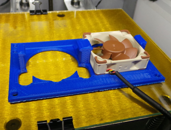
This is a new coverplate for the electronics on my Solidoodle (I have the new printrboard). It has clips for two 40mm fans you can slide under the clips and into the 40mm square depression in the top of the plate.
Note that my 12 Volt Power gadget is a nice thing to use with this to get fan power.
Using this technique I can slide the fans out for access to the vref potentiometers in case I ever need to fiddle with the settings (no need to take off the cover plate). I've included the original slots solidoodle provided for vref access (except where they were cut away by the fan holes, of course). I also included the hole for access to the reset button.
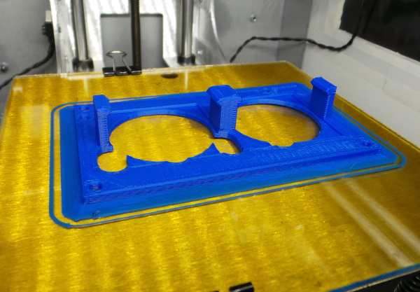
This also helped me improve the printer calibration. A small calibration test (like the nickel test) will not be sensitive enough to detect small errors which do show up in an object as large as this cover plate. The first attempt to print this wound up with the screw holes too far apart in both X and Y, even though the model exactly matched the hole positions of the original solidoodle plate.
I obtained the original plate geometry by removing the plate and using the flatbed scanner of my all-in-one printer to get a 600dpi image of the plate. Measuring the size of the plate with calipers and comparing to the image size gave me 23.6 pixels per millimeter. I was then able to use gimp to rotate the image to be exactly square and crop the scan to the exact borders of the plate. I could then make selections around all the holes and use the size and position of the selections to compute the size and positions of the holes.
That information was used in the openscad design file. A snapshot of the bottom of the image using orthogonal rendering was scaled to the exact size of the original solidoodle scan to see that the model was an exact match to the real plate.
Using much the same technique again, I scanned the bad print and compared it to the actual solidoodle plate (scanned on the same machine with the same dpi). That told me how much to scale in the X and Y directions (about 98% both ways), and I applied that to the firmware settings for X and Y.
I had also noticed that my original vertical clip pieces could snap off (guess how I noticed that :-), so I made the clips thicker (which apparently caused a problem with the STL file which I fixed in netfabb - I don't think the two middle clips were quite touching).
The second print came out much better (you see the results above), and the holes appear to line up perfectly.
I may need an additional mod to this to add a way to clip on a circuit board to hold additional fan headers and a power connector for an external 12 volt fan power supply. (Or maybe I'll just build a box I can glue on.)
Go back to my main Solidoodle page.