Bed Level Sensor
- Goose Chase
- Working Test
- Arduino Test
- Bad Mounting
- Good Mounting
- Cable
- Pins
- Firmware
- Results
- Working!
Goose Chase
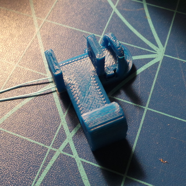
The Solidoodle extruder head wobble preventer gave me an idea for a sensor to detect the bed level. What if, instead of running the spring from the hole in that part, I plugged up the hole and made another part that slipped under the tab which I could pull up with the spring? Then what if I slipped a force sensitive resistor between the parts?
bedlevel.scad is my first hack at building the parts for this. That file imports FixedXAxisPreload.stl (which, for some reason, I had to run through netfabb cloud to make openscad happy).
I soldered a couple of long pieces of some very thin wire wrap wire I had laying around to the resistor, and taped it in place to the bottom of the top part. The complete assembly looks like:
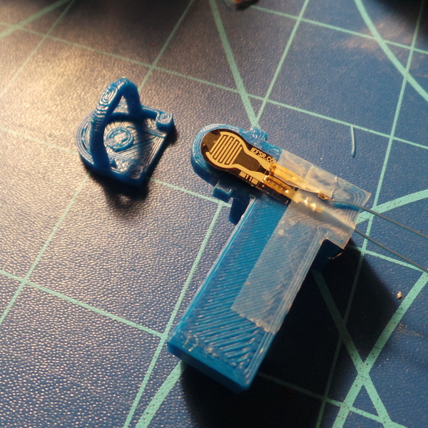
Amazingly, I didn't kill it by soldering on the leads (I had an alligator clip for a heat sink and I just barely touched the iron to the tab long enough to melt a little solder). I can see the resistance change when I press on the structure.
The next step is to get it mounted on the solidoodle and see if I can pick up changes in resistance when I raise the bed with something like a piece of cardboard on it underneath the nozzle. In theory that should make the head rock back and change the tension on the spring which will, in turn, change the resistance.
Devising a circuit to make it look like a switch to the firmware is in the far distant future and depends on how my experiments work. Possibly it would make more sense to run it through an analog input and add firmware to detect resistance changes rather than trying to do that in a hardware circuit. For now, I'll just manually monitor the resistance with a multi-meter.
Adafruit has some good info on using an FSR with an arduino which might come in handy in the future.
First try: Not so good :-). The thingiverse part above isn't wide enough for the teflon block in my solidoodle. It snapped off the support when I tried to force it. I need to redesign the part from scratch in openscad so I can adjust the dimensions. I also need to put the block back where it was so I can print the new part. I'm also realizing I need to fit a nut on the end of the bolt that will hold the block, so I need to make sure there is room for that and the lifter part.
Second try: DOH! I got the part re-implemented, and it seems to be working, I can detect a distinct resistance change of about 1K Omh when I rock the carriage. Unfortunately, the carriage doesn't rock that direction when touching the print bed. The normal geometry is for it to be back as far as it can go. I can only detect it going forward with the resistor placement in my gadget. What I really need is a way to wedge the resistor above the top teflon block. Don't know if that is possible to do.
Working Test
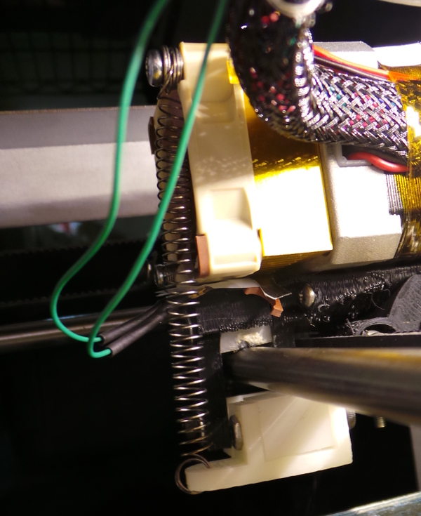
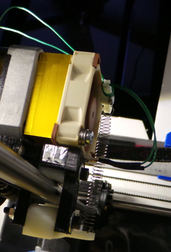
Third Time's The Charm: So, I looked around for some place to squeeze in the resistor where the force would act in the correct direction, and I noticed there was a tiny amount of space between the bottom of the fan on the extruder and the top of the X carriage. There is also enough flexibility in the parts that I could see the gap get smaller when I pushed up on the nozzle:
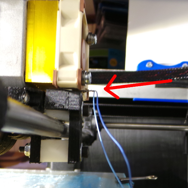
I wrapped some paper around it to try and wedge it in fairly well, and tried the experiment with raising the bed 1/10 mm at a time with a thin shim under the nozzle. The results on the multi-meter were pretty dramatic. It hovered around 39KΩ with the fractional digits flickering around a lot. Then when I moved the bed the last 1/10 of a millimeter and made contact with the shim, it jumped to 34KΩ, so the resistor does indeed appear to be sensitive enough to notice contact (and the stock solidoodle extruder does indeed seem to have quite a lot of flexing built in :-).
I think this brings an end to this phase of my experiments. It will take some thought to come up with a more acceptable and permanent way to mount this. The resistor wrapped in paper isn't really very secure, but the general idea looks promising, and I could have avoided a lot of work if I had tried this first.
The soliforum Bed Level Sensor experiment thread seems to be accumulating lots of good advice about fiddling with the firmware to implement this new style sensor, so that will be something to investigate when I have time to rig up a more permanent mount for the sensor.
I've also tracked down the information I need to compile the firmware.
Meanwhile, while working on my bed heater upgrade, I've soldered all the missing headers onto the printrboard, so I now have pins available to hook up the resistor to an analog input (there appear to be a couple of spares not being used right now), so that should make it possible to see if I can have the printrboard see the resistance change.
Arduino Test
After a delay, I'm back looking at this, and I've just breadboarded up a circuit to hook up the FSR to an Arduino Uno I happen to have (I can make sure things work on this stand alone arduino before I try to integrate this with the Marlin firmware). Dead simple circuit looks like this:
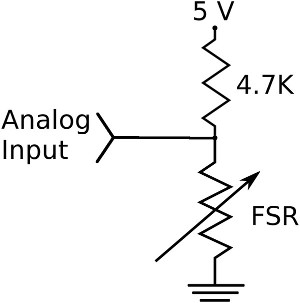
This sketch loaded into the arduino:
int fsrAnalogPin = 0; // FSR is connected to analog 0
int fsrReading; // the analog reading from the FSR resistor divider

void setup(void) {
   Serial.begin(9600); // We'll send debugging information via the Serial monitor
}

void loop(void) {
   fsrReading = analogRead(fsrAnalogPin);
   Serial.print("Analog reading = ");
   Serial.println(fsrReading);
   delay(100);
}
Will spew a series of samples endlessly, and when I connect to the serial port and watch the data, I can see it change from 1023 with no pressure applied down to a few hundred as I squeeze the resistor.
So I can successfully convert the resistance to a voltage level I can measure with an arduino analog input. Now I need to rig up a more solid mounting than wrapping it in a piece of paper and get it in my solidoodle to see if it is sensitive enough to detect the change when the nozzle touches the print bed. Might need to fiddle the fixed resistor value to get a good range.
Bad Mounting
Well, I made one try at a new mounting, printing some thin plastic parts to sandwich it under the fan, but it didn't work worth spit. I think I almost completely missed the short segment of carriage under the fan which I need to compress the FSR, plus the plastic made the FSR much less sensitive. I guess I should try something much simpler like just taping the FSR to the top of the carriage in the back, perhaps with a few layers of tape to make sure the fan compresses the FSR.
Tried the tape thing too. Seemed like it might work, but it is apparently very tricky to get the FSR in just the right spot for the fan to press down on it. So far my first experiment with folded paper has worked better than any permanent solution I've tried to come up with :-).
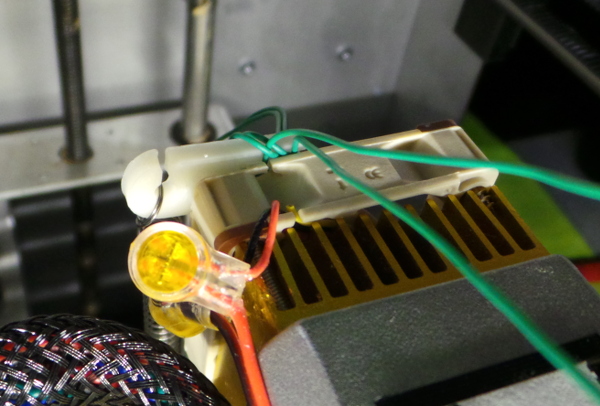
After many fiddlings, I finally got the FSR taped down (not very solidly, I'm afraid) with it overhanging the edge of the back part of the carriage (the part that holds the teflon block). It seems to be pretty responsive in this position, but I don't know how long it will stay in place. The photo shows it has already rotated a little bit from where I initially taped it:
Watching the resistance with a multimeter I can definitely see it change as the nozzle hits a shim placed under it when I raise the bed, but I can also see it change as the head moves side to side and the wires (which I have tied to the wiring harness with some thread) get tugged on a bit. I'll definitely want to ignore changes in resistance when moving any direction other than up and down.
I'm thinking what I really want to do is print something that can be screwed down with the fan to provide a place to anchor the wires solidly. If it substituted for the stack of washers on each screw I could also print a hook out to the side on the top to attach the spring for my springloader instead of having to run the screw through the top loop.
Good Mounting
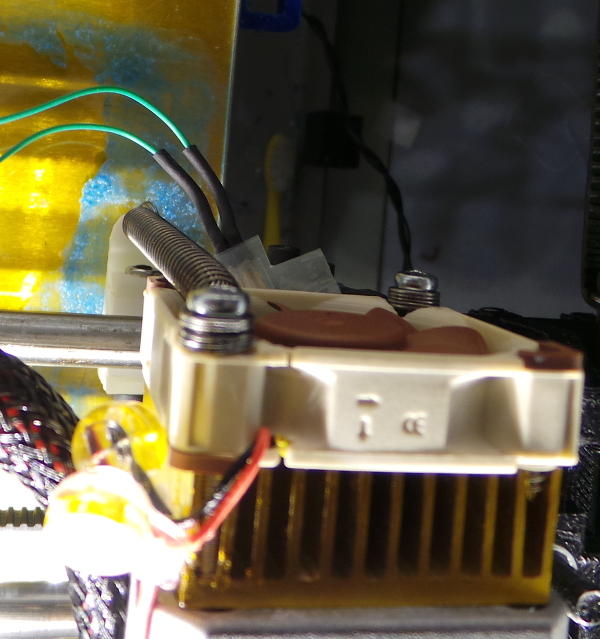
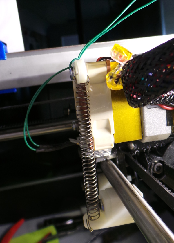
OK, after much fiddling, I've created a silly part to go on the fan instead of the stack of washers, and I've got the FSR re-taped to the back of the carriage and the wires anchored so they don't get tugged by any carriage movement. It took a lot of fiddling to get the FSR positioned right. I had to tape some shims on top of it, and also make sure I pushed down on the fan as I screwed it back into the extruder assembly so that the FSR is squeezed a bit even when the nozzle isn't touching anything. I used an ohm meter to monitor it while getting everything assembled (an extra hand or two would have made that less tricky :-). Anyway, I finally got the FSR positioned, and the wires solidly anchored to the part I printed which is solidly held down by the screw through the fan:
After successful tests with the ohm meter, I hooked the wires back into my breadboard test circuit with the Arduino Uno. I captured the sample spewing as I raised and lowered the bed. With nothing on the bed, the values didn't look different when I raised the bed, but with a brass shim (which my caliper says is 0.08mm thick) under the nozzle, I could see a slight variation in the voltage samples being taken when I raised the bed. Using kermit to capture the log of samples, I whipped out a perl script to print the running average of the last 5 samples to see what it looked like when smoothed out, and there is indeed a slight, but consistent and measurable variation as the level changes:
18:12:46.653:  Smoothed reading = 762
18:12:46.756:  Smoothed reading = 762
18:12:46.854:  Smoothed reading = 762
18:12:46.956:  Smoothed reading = 762
18:12:47.055:  Smoothed reading = 762
...
18:12:49.766:  Smoothed reading = 760
18:12:49.864:  Smoothed reading = 760
18:12:49.967:  Smoothed reading = 760
18:12:50.065:  Smoothed reading = 760
18:12:50.167:  Smoothed reading = 760
...
18:13:15.852:  Smoothed reading = 762
18:13:15.950:  Smoothed reading = 762
18:13:16.052:  Smoothed reading = 762
18:13:16.151:  Smoothed reading = 762
18:13:16.253:  Smoothed reading = 762
18:13:16.351:  Smoothed reading = 762
So, the theory all seems to be working out. Average a few samples and I can tell when the nozzle has just touched the print bed. All that remains is the hard part (like trying to find the best version of the Marlin source code I should start with when trying to integrate this with the firmware on the printrboard instead of a stand alone arduino).
Cable
I need to cobble up the cable that will actually connect to the printrboard headers. I soldered the resistor inline and used lots of heat shrink tubing to wrap everything up, then I frankensteined the ends of the cables to some little wires (might have been from a USB motherboard cable) with push on connectors that will fit the pins:
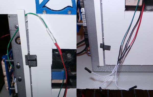
That gives me a red wire to connect to +5V, and black wire to connect to ground, and a green wire to connect to whatever analog input I find that is un-used on the printrboard.
Hooking it to the Arduino Uno one last time shows that everything is still functioning with the new cable, so I guess I managed to put it together correctly. Once I figure out what pins to use, I should be all set.
Pins
Poked around in the eagle files. I see the bed thermistor is ADC0 which is on pin 61, the extruder thermistor is ADC1 which is on pin 60 and ADC2 on pin 59 doesn't seem to be used by anyone. Using the Show function in the eagle software I can see the pin 60 and 61 do indeed highlight a path to the connectors for the thermistors, so pin 59 should be the next one over, and when I highlight it, the path goes to pin 2 on the 14 pin header JP2 over by the edge of the printrboard. Pin 2 on that connector is the inside pin at the bottom. That connector also has +5V on the outside pin at the top and ground on the inside pin at the top, so now I know how to hook up the FSR to the printrboard:
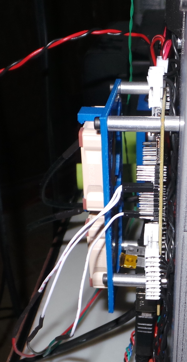
The printer seems to function correctly after hooking this up, so I guess I still haven't managed to break it :-). The only thing left is firmware.
Firmware
I've been documenting my basic procedures for dealing with new firmware on the Solidoodle Firmware page. Here, I'm trying to figure out exactly what to do for the FSR sensor.
Poking around in the code reminded me of how much Atmel programming I've forgotten since the last time I was working on a project with one of these chips.
My initial idea (subject to major changes as I learn more) is to treat the FSR a lot like a thermistor. I see the temperature.cpp file has an interrupt routine ISR(TIMER0_COMPB_vect) where (if I grasp the idea) it is cycling through the different thermistors and reading the values. I suspect I'll want to add my FSR to the regular sampling going on in there. But whatever I do will take more study.
Probably the first thing to do is just add a command for testing that will print the current running average from the FSR input. I can run that manually just to see if I'm really reading the pin I think I ought to be reading. Once I see that working, I can deal with the more complicated task of integration with the automatic bed level code in Marlin.
In the pins.h file I see the pins being defined for the thermistors using the analog input numbers, so for printrboard, I see this:
  #define TEMP_0_PIN          1  // Extruder / Analog pin numbering
  #define TEMP_BED_PIN        0  // Bed / Analog pin numbering
That means I'd want the pin number for my FSR to be 2 (for analog input 2).
Taking a closer look at temperature.cpp I see initialization happening in tp_init(). Stuff like this is happening for the analog input pins:
  #if defined(TEMP_BED_PIN) && (TEMP_BED_PIN > -1)
    #if TEMP_BED_PIN < 8
       DIDR0 |= 1<<TEMP_BED_PIN;
    #else
       DIDR2 |= 1<<(TEMP_BED_PIN - 8);
    #endif
  #endif
That bit appears to be disabling digital input on the ADC pins (section 8.8.6 in the manual recommends this).
The next time I see the bed temp referenced is in the TIMER0_COMPB_vect interrupt routine:
    case 2: // Prepare TEMP_BED
      #if defined(TEMP_BED_PIN) && (TEMP_BED_PIN > -1)
        #if TEMP_BED_PIN > 7
          ADCSRB = 1<<MUX5;
        #else
          ADCSRB = 0;
        #endif
        ADMUX = ((1 << REFS0) | (TEMP_BED_PIN & 0x07));
        ADCSRA |= 1<<ADSC; // Start conversion
      #endif
      lcd_buttons_update();
      temp_state = 3;
      break;
    case 3: // Measure TEMP_BED
      #if defined(TEMP_BED_PIN) && (TEMP_BED_PIN > -1)
        raw_temp_bed_value += ADC;
      #endif
      temp_state = 4;
      break;
This code appears to be running through a state machine with 8 states, each preparing an ADC then reading an ADC. This gives rise to my first confusion. It will apparently go through all 8 states even if some of the ADCs are ifdefed out. Does this mean it is counting on the ADC samples to occur at a known fixed rate? If so, I'll be in trouble if I add two new states for my FSR. I could certainly kludge things for testing by using one of the state pairs I happen to know isn't used by the printrboard to run the FSR instead, but that clearly wouldn't be a good long term fix that would integrate well back into the official source. Eventually, I'll need to find out how important the 8 states are in this state machine. On the other hand, maybe it just means the code is only designed to support a max of 4 ADC readings and the timing isn't important? (Nope, I see code computing times based on just knowing how long it takes to make it through all 8 states).
I see a TEMP_SENSOR_1_AS_REDUNDANT flag in the code, so that provides a partial precedent for a define to change the meaning of a single sensor. In the interest of getting something to work, I guess I'll invent something like TEMP_SENSOR_2_IS_FSR and ifdef the folks using temp 2 to compute a running average for the FSR value instead. This means no FSR on a dual extruder machine, but you can't have everything (at least not without a much bigger revision of the firmware :-).
Gahh! There are TEMP_SENSOR defines, TEMP_PIN defines. I can't figure out how they all interact or what the definitions mean. I'm going to be very heavy handed with hacking this code I'm afraid, but get it to work first, make it elegant second...
Well, I hacked in some code to make TEMP_2_PIN be my FSR and added the M403 command to print the value it accumulates. Unfortunately, it always prints 0 (sigh). I guess I need to check and see if the pins are really connected where I think they are connected. This will take some poking around...
A voltmeter confirms I see 5V across the top two pins. I could try using A3 instead of A2 as my input pin, it is just one up from A2, maybe the header didn't get connected right for A2? Worth a try anyway... Nope, I get the same results, always zero.
New experiment: I unplugged the bed heater thermistor and plugged in the FSR green and black wires where the bed heater was. That seems to work fine. I get about 71 degrees according to RH, which goes up to about 78 degrees when I press up on the nozzle. So the FSR is working, the ADC converter is working, but I can't get a signal on the A2 or A3 connections through the header. I'll have to pull the board out and probe the connections to see if I screwed up something when soldering in the headers.
DOH! Nothing as esoteric as a screwed up connection. Instead I just had a typo in my code that failed to actually record the values I read from the analog pin. Here's what I now see from my test command:
20:10:21.337 : FSR:12601.00 COUNT: 6608 SAMPLES: 12602 12600 12601 12601 12601
20:10:56.118 : FSR:11712.00 COUNT: 15100 SAMPLES: 11699 11727 11712 11712 11710
The first M403 command was with the nozzle just sitting there, the second was with me pressing up on the nozzle. So I can actually see the values in the firmware and notice a change when the nozzle is touched. I'm finally ready to figure out how to integrate this with the existing bedlevel code. (Some of that output above is just debug code telling me I've actually been executing the interrupt code and what the raw samples were). Here are the changes I made:
--- Marlin/Configuration.h	2013-12-07 04:31:28.000000000 -0500
+++ Marlin/Configuration.h	2014-01-05 13:49:42.120582949 -0500
@@ -19,7 +19,7 @@
 #define STRING_CONFIG_H_AUTHOR "Adrian/Lawsy/Rincewind/Tealvince" // Who made the changes.

 // change to 3 for SD3 //{SD Patch}
-#define SOLIDOODLE_VERSION 3 //{SD Patch}
+#define SOLIDOODLE_VERSION 2 //{SD Patch}

 // Enable support for either of the Z-Wobble Solutions
 //#define ZWOBBLE_PATCH //{SD Patch} (+5528 Bytes)
@@ -78,9 +78,19 @@
 // Original Solidoodle w/ Sanguinololu shipped pre June 2013 - Choose 62
 // Solidoodle w/ Printrboard shipped post June 2013 - Choose 81
 #ifndef MOTHERBOARD
-#define MOTHERBOARD 62
+#define MOTHERBOARD 81
 #endif

+// This is a hacky definition that is designed to get my force sensitive resistor
+// as bed level detctor working. It will cause TEMP_PIN_2 to monitor the analog
+// value of the force sensitive resistor rather than a thermistor. Define it to
+// be the analog pin number where the FSR is connected (or -1 for no FSR).
+#define TEMP_2_PIN_IS_BEDLEVEL_FSR 3
+
+// If a bedleve FSR is installed, this is the number of samples to accumulate
+// to provide a smoothed out running average
+#define BEDLEVEL_FSR_SAMPLE_COUNT 5
+
 // Define this to set a custom name for your generic Mendel,
 // #define CUSTOM_MENDEL_NAME "This Mendel"

--- Marlin/Marlin_main.cpp	2013-12-07 04:31:28.000000000 -0500
+++ Marlin/Marlin_main.cpp	2014-01-05 18:45:23.577528455 -0500
@@ -160,6 +160,7 @@
 // M400 - Finish all moves
 // M401 - Lower z-probe if present
 // M402 - Raise z-probe if present
+// M402 - report bedlevel FSR smoothed average value
 // M500 - stores paramters in EEPROM
 // M501 - reads parameters from EEPROM (if you need reset them after you changed them temporarily).
 // M502 - reverts to the default "factory settings".  You still need to store them in EEPROM afterwards if you want to.
@@ -973,6 +974,28 @@

 #endif // #ifdef ENABLE_AUTO_BED_LEVELING

+#if TEMP_2_PIN_IS_BEDLEVEL_FSR != -1
+
+static void report_bedlevel_fsr() {
+   float avg = 0.0;
+   for (int i = 0; i < BEDLEVEL_FSR_SAMPLE_COUNT; ++i) {
+      avg += (float)bedlevel_fsr_samples[i];
+   }
+   avg /= (float)BEDLEVEL_FSR_SAMPLE_COUNT;
+   SERIAL_PROTOCOLPGM("FSR:");
+   SERIAL_PROTOCOL(avg);
+   SERIAL_PROTOCOL(" COUNT: ");
+   SERIAL_PROTOCOL(bedlevel_count);
+   SERIAL_PROTOCOL(" SAMPLES:");
+   for (int i = 0; i < BEDLEVEL_FSR_SAMPLE_COUNT; ++i) {
+      SERIAL_PROTOCOL(" ");
+      SERIAL_PROTOCOL(bedlevel_fsr_samples[i]);
+   }
+   SERIAL_PROTOCOLLN("");
+}
+
+#endif
+
 static void homeaxis(int axis) {
 #define HOMEAXIS_DO(LETTER) \
   ((LETTER##_MIN_PIN > -1 && LETTER##_HOME_DIR==-1) || (LETTER##_MAX_PIN > -1 && LETTER##_HOME_DIR==1))
@@ -2579,6 +2602,13 @@
     }
     break;
 #endif
+#if TEMP_2_PIN_IS_BEDLEVEL_FSR != -1
+    case 403:
+    {
+        report_bedlevel_fsr(); // Report the bedlevel FSR running average
+    }
+    break;
+#endif
     case 500: // M500 Store settings in EEPROM
     {
         Config_StoreSettings();
--- Marlin/pins.h	2013-12-07 04:31:28.000000000 -0500
+++ Marlin/pins.h	2014-01-05 10:07:46.258029404 -0500
@@ -1464,7 +1464,7 @@
 #endif

 #define TEMP_1_PIN         -1
-#define TEMP_2_PIN         -1
+#define TEMP_2_PIN         TEMP_2_PIN_IS_BEDLEVEL_FSR

 #define SDPOWER            -1
 #define SDSS               14
--- Marlin/temperature.h	2013-12-07 04:31:28.000000000 -0500
+++ Marlin/temperature.h	2014-01-05 15:11:17.872809832 -0500
@@ -44,6 +44,10 @@
 #ifdef TEMP_SENSOR_1_AS_REDUNDANT
   extern float redundant_temperature;
 #endif
+#if TEMP_2_PIN_IS_BEDLEVEL_FSR != -1
+  extern int bedlevel_fsr_samples[BEDLEVEL_FSR_SAMPLE_COUNT];
+  extern int bedlevel_count;
+#endif

 #if defined(CONTROLLERFAN_PIN) && CONTROLLERFAN_PIN > -1
   extern unsigned char soft_pwm_bed;
--- Marlin/temperature.cpp	2013-12-07 04:31:28.000000000 -0500
+++ Marlin/temperature.cpp	2014-01-05 20:05:31.036547555 -0500
@@ -47,6 +47,12 @@
   int redundant_temperature_raw = 0;
   float redundant_temperature = 0.0;
 #endif
+#if TEMP_2_PIN_IS_BEDLEVEL_FSR != -1
+  int bedlevel_fsr_raw = 0;
+  int bedlevel_fsr_samples[BEDLEVEL_FSR_SAMPLE_COUNT] = { 0 };
+  int bedlevel_fsr_next_sample = 0;
+  int bedlevel_count = 0;
+#endif
 #ifdef PIDTEMP
   float Kp=DEFAULT_Kp;
   float Ki=(DEFAULT_Ki*PID_dT);
@@ -684,6 +690,12 @@
     #ifdef TEMP_SENSOR_1_AS_REDUNDANT
       redundant_temperature = analog2temp(redundant_temperature_raw, 1);
     #endif
+    #if TEMP_2_PIN_IS_BEDLEVEL_FSR != -1
+      bedlevel_fsr_samples[bedlevel_fsr_next_sample++] = bedlevel_fsr_raw;
+      if (bedlevel_fsr_next_sample == BEDLEVEL_FSR_SAMPLE_COUNT) {
+        bedlevel_fsr_next_sample = 0;
+      }
+    #endif
     //Reset the watchdog after we know we have a temperature measurement.
     watchdog_reset();

@@ -916,13 +928,15 @@
     #endif
   #endif

-  #if defined(TEMP_2_PIN) && TEMP_2_PIN > -1
-    target_temperature[2]=0;
-    soft_pwm[2]=0;
-    #if defined(HEATER_2_PIN) && HEATER_2_PIN > -1
-      WRITE(HEATER_2_PIN,LOW);
-    #endif
-  #endif
+  #if TEMP_2_PIN_IS_BEDLEVEL_FSR == -1
+    #if defined(TEMP_2_PIN) && TEMP_2_PIN > -1
+      target_temperature[2]=0;
+      soft_pwm[2]=0;
+      #if defined(HEATER_2_PIN) && HEATER_2_PIN > -1
+        WRITE(HEATER_2_PIN,LOW);
+      #endif
+    #endif
+  #endif

   #if defined(TEMP_BED_PIN) && TEMP_BED_PIN > -1
     target_temperature_bed=0;
@@ -1170,6 +1184,7 @@
         #endif
         ADMUX = ((1 << REFS0) | (TEMP_2_PIN & 0x07));
         ADCSRA |= 1<<ADSC; // Start conversion
+        bedlevel_count++;
       #endif
       lcd_buttons_update();
       temp_state = 7;
@@ -1177,6 +1192,7 @@
     case 7: // Measure TEMP_2
       #if defined(TEMP_2_PIN) && (TEMP_2_PIN > -1)
         raw_temp_2_value += ADC;
+        bedlevel_count++;
       #endif
       temp_state = 0;
       temp_count++;
@@ -1198,6 +1214,9 @@
 #ifdef TEMP_SENSOR_1_AS_REDUNDANT
       redundant_temperature_raw = raw_temp_1_value;
 #endif
+#if TEMP_2_PIN_IS_BEDLEVEL_FSR != -1
+      bedlevel_fsr_raw = raw_temp_2_value;
+#endif
 #if EXTRUDERS > 2
       current_temperature_raw[2] = raw_temp_2_value;
 #endif
I'm poking around in the code trying to figure out how to do all the low level movement I need to do to sneak up on the bed level without crashing the nozzle into the bed. Some things I'll probably find useful:
extern void StartBedlevelFsrSample(); is a new routine I've added to start collecting sample FSR values. I can call it when I know I'm not moving to collect several values I can average.
extern float WaitForBedlevelFsrSample(); is the routine that waits for several samples to be collected, then returns the average (might want to change it to throw out max and min and average the rest).
extern float axis_steps_per_unit[4]; The array holds the info about how many steps are required to move 1mm (I guess you can configure the units, but mm is what it really is). The Z axis is the one I'll be moving and is index 2 in the array. I can deduce from this what the smallest movement I can make is (a single step if I ignore microstepping which I certainly intend to do for now :-). [I see that my printer says steps per mm on the Z axis is 2268, so if that can be believed a single step will only move 0.44 microns. That's a heck of a small movement for a single step. I doubt if I can really measure bed level accurately enough to worry about such small distances, or that the mechanism is precise enough to really move exactly that much. Clearly microstepping isn't something to worry about.]
plan_buffer_line() is the routine that buffers up some planned movement for the steppers to execute.
st_synchronize() is the routine which waits for all movement to be completed.
void enable_endstops(bool check); can be used to turn on and off checking for hitting the endstops.
endstops_hit_on_purpose() can be used to clear the flags saying the endstop is already hit.
I think what I'm going to want to do is physically adjust the Z endstop screw to always stop the nozzle slightly above the print bed. Then define ENDSTOPS_ONLY_FOR_HOMING so normal movement can go past the Z endstop once I figure out the actual bed level with the sensor. (Also Z_SAFE_HOMING looks like an excellent flag to enable.)
To figure the actual bed level, I'll modify static void run_z_probe() to turn on the endstops, move to the Z endstop, then turn off endstops and very slowly move the nozzle closer to the bed till the FSR value shows an obvious change from before and after movement.
At least that is the theory. We'll see how it works when I get the code written.
Results
Time has passed, and I finally got time to work on this again and wrote some additional code for the run_z_probe() routine, activated all the ifdefs for bed leveling, corrected the probe positions for my solidoodle 2 with no probe offset, and I can run a G29 detailed probe and it seems to work! Here's one I did after cranking down one leveling screw. This bit of log from RH certainly looks as if it is getting different Z values in different corners:
< 16:05:20.641 : N23 G29 *3
> 16:05:49.381 : Bed x: 15 y: 15 z: 0.01
> 16:06:14.286 : Bed x: 15 y: 135 z: 0.01
> 16:06:50.722 : Bed x: 135 y: 15 z: 0.02
> 16:07:13.659 : Bed x: 135 y: 135 z: 0.03
> 16:07:13.665 : Eqn coefficients: a: 0.00 b: 0.00 d: 0.01
> 16:07:13.665 : planeNormal x: -0.00 y: -0.00 z: 1.00
> 16:07:13.665 : bed level before
> 16:07:13.665 : 1.00 0.00 0.00
> 16:07:13.669 : 0.00 1.00 0.00
> 16:07:13.669 : -0.00 -0.00 1.00
> 16:07:13.669 : ok
I don't really understand all the stuff it printed above. A lot of it appears to be some debug code that isn't commented out (but a lot of other debug code is commented out). Now I'm guessing that I need to run the G29 as part of the start code, but I should find out for sure...
Working!
I found some stupid typos in my code, and it all seems to be working now! At this moment, I'm printing 4 perfect little test cubes on a print bed that has had one leveling screw cranked down by a couple of millimeters and has had the z-stop screw cranked down by about a millimeter. Without the bed level code, this would just print strands of plastic in air.
And here are the results:
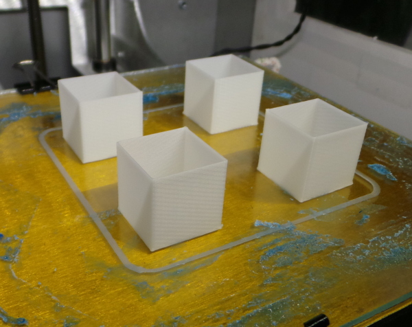
Note the wonderfully smooth and uniform skirt around the cubes.
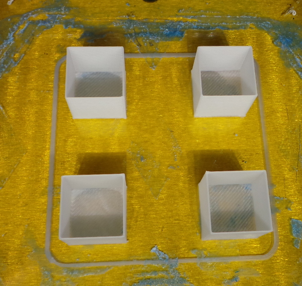
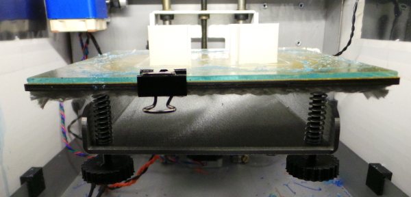
Here you can (maybe) see how the left side of the print bed has been cranked down:
Here's the changes I made to the firmware to get this working:
--- Marlin/Configuration.h	2013-12-07 04:31:28.000000000 -0500
+++ Marlin/Configuration.h	2014-01-18 14:07:25.617772061 -0500
@@ -19,7 +19,7 @@
 #define STRING_CONFIG_H_AUTHOR "Adrian/Lawsy/Rincewind/Tealvince" // Who made the changes.

 // change to 3 for SD3 //{SD Patch}
-#define SOLIDOODLE_VERSION 3 //{SD Patch}
+#define SOLIDOODLE_VERSION 2 //{SD Patch}

 // Enable support for either of the Z-Wobble Solutions
 //#define ZWOBBLE_PATCH //{SD Patch} (+5528 Bytes)
@@ -78,9 +78,27 @@
 // Original Solidoodle w/ Sanguinololu shipped pre June 2013 - Choose 62
 // Solidoodle w/ Printrboard shipped post June 2013 - Choose 81
 #ifndef MOTHERBOARD
-#define MOTHERBOARD 62
+#define MOTHERBOARD 81
 #endif

+#define ENABLE_AUTO_BED_LEVELING
+
+// This is a hacky definition that is designed to get my force sensitive resistor
+// as bed level detctor working. It will cause TEMP_PIN_2 to monitor the analog
+// value of the force sensitive resistor rather than a thermistor. Define it to
+// be the analog pin number where the FSR is connected (or -1 for no FSR).
+#define TEMP_2_PIN_IS_BEDLEVEL_FSR 3
+
+// If a bedleve FSR is installed, this is the number of samples to accumulate
+// to provide a smoothed out running average
+#define BEDLEVEL_FSR_SAMPLE_COUNT 5
+
+#define BEDLEVEL_FSR_MAX_MOVE_INC 0.1
+#define BEDLEVEL_FSR_MIN_MOVE_INC 0.01
+
+#define ENDSTOPS_ONLY_FOR_HOMING
+#define Z_SAFE_HOMING
+
 // Define this to set a custom name for your generic Mendel,
 // #define CUSTOM_MENDEL_NAME "This Mendel"

@@ -349,14 +367,14 @@

   // these are the positions on the bed to do the probing
   #define LEFT_PROBE_BED_POSITION 15
-  #define RIGHT_PROBE_BED_POSITION 170
-  #define BACK_PROBE_BED_POSITION 180
-  #define FRONT_PROBE_BED_POSITION 20
+  #define RIGHT_PROBE_BED_POSITION 135
+  #define BACK_PROBE_BED_POSITION 135
+  #define FRONT_PROBE_BED_POSITION 15

   // these are the offsets to the prob relative to the extruder tip (Hotend - Probe)
-  #define X_PROBE_OFFSET_FROM_EXTRUDER -25
-  #define Y_PROBE_OFFSET_FROM_EXTRUDER -29
-  #define Z_PROBE_OFFSET_FROM_EXTRUDER -12.35
+  #define X_PROBE_OFFSET_FROM_EXTRUDER 0
+  #define Y_PROBE_OFFSET_FROM_EXTRUDER 0
+  #define Z_PROBE_OFFSET_FROM_EXTRUDER 0

   #define Z_RAISE_BEFORE_HOMING 4       // (in mm) Raise Z before homing (G28) for Probe Clearance.
                                         // Be sure you have this distance over your Z_MAX_POS in case
@@ -371,7 +389,7 @@
   //The value is the delay to turn the servo off after powered on - depends on the servo speed; 300ms is good value, but you can try lower it.
   // You MUST HAVE the SERVO_ENDSTOPS defined to use here a value higher than zero otherwise your code will not compile.

-  #define PROBE_SERVO_DEACTIVATION_DELAY 300
+  #define PROBE_SERVO_DEACTIVATION_DELAY 0


 //If you have enabled the Bed Auto Levelling and are using the same Z Probe for Z Homing,
--- Marlin/Marlin_main.cpp	2013-12-07 04:31:28.000000000 -0500
+++ Marlin/Marlin_main.cpp	2014-01-20 19:54:37.955383342 -0500
@@ -160,6 +160,7 @@
 // M400 - Finish all moves
 // M401 - Lower z-probe if present
 // M402 - Raise z-probe if present
+// M402 - report bedlevel FSR smoothed average value
 // M500 - stores paramters in EEPROM
 // M501 - reads parameters from EEPROM (if you need reset them after you changed them temporarily).
 // M502 - reverts to the default "factory settings".  You still need to store them in EEPROM afterwards if you want to.
@@ -874,6 +875,9 @@
 #endif // ACCURATE_BED_LEVELING

 static void run_z_probe() {
+#if defined(TEMP_2_PIN_IS_BEDLEVEL_FSR) && (TEMP_2_PIN_IS_BEDLEVEL_FSR != -1)
+    enable_endstops(true);
+#endif
     plan_bed_level_matrix.set_to_identity();
     feedrate = homing_feedrate[Z_AXIS];

@@ -900,6 +904,92 @@
     current_position[Z_AXIS] = st_get_position_mm(Z_AXIS);
     // make sure the planner knows where we are as it may be a bit different than we last said to move to
     plan_set_position(current_position[X_AXIS], current_position[Y_AXIS], current_position[Z_AXIS], current_position[E_AXIS]);
+
+#if defined(TEMP_2_PIN_IS_BEDLEVEL_FSR) && (TEMP_2_PIN_IS_BEDLEVEL_FSR != -1)
+
+    // The code above got use moved to the Z endstop, but the actual bed
+    // level needs to be detected by a change in the FSR value from the
+    // nozzle touching the bed, so disable the endstop check and try to
+    // move a little bit more to zero in on exactly where the bed is
+    // under the nozzle. Need to be careful here - don't want to crash into
+    // the bed or keep moving a long time after hitting it.
+
+    enable_endstops(false);
+    endstops_hit_on_purpose();
+
+    float max_move_inc = BEDLEVEL_FSR_MAX_MOVE_INC;
+    float min_move_inc = BEDLEVEL_FSR_MIN_MOVE_INC;
+
+    float move_inc = max_move_inc;
+    for ( ; ; ) {
+
+       // While we are motionless and sitting above the bed, read the
+       // FSR value to get a base value to compare with.
+
+       StartBedlevelFsrSample();
+       float base_fsr = WaitForBedlevelFsrSample();
+       float base_var = GetBedlevelVariation();
+
+   SERIAL_PROTOCOLPGM("base FSR:");
+   SERIAL_PROTOCOL(base_fsr);
+   SERIAL_PROTOCOLPGM(" base VAR:");
+   SERIAL_PROTOCOL(base_var);
+   SERIAL_PROTOCOLPGM(" move inc:");
+   SERIAL_PROTOCOL(move_inc);
+   SERIAL_PROTOCOLPGM(" current Z:");
+   SERIAL_PROTOCOL(current_position[Z_AXIS]);
+   SERIAL_PROTOCOLLN("");
+
+       base_var *= 3.0;
+
+       // Now move down "move_inc" at a time till we get a new FSR value
+       // outside of the base +/- variation.
+
+       for ( ; ; ) {
+          plan_buffer_line(current_position[X_AXIS],
+                           current_position[Y_AXIS],
+                           current_position[Z_AXIS] - move_inc,
+                           current_position[E_AXIS],
+                           feedrate/60,
+                           active_extruder);
+          st_synchronize();
+          current_position[Z_AXIS] = st_get_position_mm(Z_AXIS);
+
+          StartBedlevelFsrSample();
+          float cur_fsr = WaitForBedlevelFsrSample();
+          SERIAL_PROTOCOLPGM("cur FSR:");
+          SERIAL_PROTOCOL(cur_fsr);
+          SERIAL_PROTOCOLPGM(" current Z:");
+          SERIAL_PROTOCOL(current_position[Z_AXIS]);
+          SERIAL_PROTOCOLLN("");
+          if ((cur_fsr < (base_fsr - base_var)) ||
+              (cur_fsr > (base_fsr + base_var))) {
+             // The FSR values changed to be outside the base sample range,
+             // assume we touched the bed.
+             break;
+          }
+       }
+       if (move_inc <= min_move_inc) {
+          // We just moved into contact with the bed by the smallest move
+          // we want to make. Our work here is done.
+          break;
+       }
+       // Nove move back up above the bed and cut the size of the move
+       // in half and try again to get a more accurate position if possible.
+       plan_buffer_line(current_position[X_AXIS],
+                        current_position[Y_AXIS],
+                        current_position[Z_AXIS] + move_inc,
+                        current_position[E_AXIS],
+                        feedrate/60,
+                        active_extruder);
+       st_synchronize();
+       current_position[Z_AXIS] = st_get_position_mm(Z_AXIS);
+       move_inc /= 2.0;
+    }
+
+    // make sure the planner knows where we are as it may be a bit different than we last said to move to
+    plan_set_position(current_position[X_AXIS], current_position[Y_AXIS], current_position[Z_AXIS], current_position[E_AXIS]);
+#endif
 }

 static void do_blocking_move_to(float x, float y, float z) {
@@ -973,6 +1063,18 @@

 #endif // #ifdef ENABLE_AUTO_BED_LEVELING

+#if defined(TEMP_2_PIN_IS_BEDLEVEL_FSR) && (TEMP_2_PIN_IS_BEDLEVEL_FSR != -1)
+
+static void report_bedlevel_fsr() {
+   StartBedlevelFsrSample();
+   float avg = WaitForBedlevelFsrSample();
+   SERIAL_PROTOCOLPGM("FSR:");
+   SERIAL_PROTOCOL(avg);
+   SERIAL_PROTOCOLLN("");
+}
+
+#endif
+
 static void homeaxis(int axis) {
 #define HOMEAXIS_DO(LETTER) \
   ((LETTER##_MIN_PIN > -1 && LETTER##_HOME_DIR==-1) || (LETTER##_MAX_PIN > -1 && LETTER##_HOME_DIR==1))
@@ -2579,6 +2681,19 @@
     }
     break;
 #endif
+#if defined(TEMP_2_PIN_IS_BEDLEVEL_FSR) && (TEMP_2_PIN_IS_BEDLEVEL_FSR != -1)
+    case 403:
+    {
+        report_bedlevel_fsr(); // Report the bedlevel FSR running average
+    }
+    break;
+    case 404:
+    {
+        enable_endstops(false) ;
+        endstops_hit_on_purpose();
+    }
+    break;
+#endif
     case 500: // M500 Store settings in EEPROM
     {
         Config_StoreSettings();
--- Marlin/pins.h	2013-12-07 04:31:28.000000000 -0500
+++ Marlin/pins.h	2014-01-13 17:29:44.743057968 -0500
@@ -1464,7 +1464,11 @@
 #endif

 #define TEMP_1_PIN         -1
+#if defined(TEMP_2_PIN_IS_BEDLEVEL_FSR)
+#define TEMP_2_PIN         TEMP_2_PIN_IS_BEDLEVEL_FSR
+#else
 #define TEMP_2_PIN         -1
+#endif

 #define SDPOWER            -1
 #define SDSS               14
--- Marlin/temperature.h	2013-12-07 04:31:28.000000000 -0500
+++ Marlin/temperature.h	2014-01-18 12:36:42.589824254 -0500
@@ -44,6 +44,11 @@
 #ifdef TEMP_SENSOR_1_AS_REDUNDANT
   extern float redundant_temperature;
 #endif
+#if defined(TEMP_2_PIN_IS_BEDLEVEL_FSR) && (TEMP_2_PIN_IS_BEDLEVEL_FSR != -1)
+  extern void StartBedlevelFsrSample();
+  extern float WaitForBedlevelFsrSample();
+  extern float GetBedlevelVariation();
+#endif

 #if defined(CONTROLLERFAN_PIN) && CONTROLLERFAN_PIN > -1
   extern unsigned char soft_pwm_bed;
--- Marlin/temperature.cpp	2013-12-07 04:31:28.000000000 -0500
+++ Marlin/temperature.cpp	2014-01-18 12:45:58.043066624 -0500
@@ -47,6 +47,10 @@
   int redundant_temperature_raw = 0;
   float redundant_temperature = 0.0;
 #endif
+#if defined(TEMP_2_PIN_IS_BEDLEVEL_FSR) && (TEMP_2_PIN_IS_BEDLEVEL_FSR != -1)
+  int bedlevel_fsr_samples[BEDLEVEL_FSR_SAMPLE_COUNT] = { 0 };
+  volatile unsigned char bedlevel_fsr_next_sample = 0;
+#endif
 #ifdef PIDTEMP
   float Kp=DEFAULT_Kp;
   float Ki=(DEFAULT_Ki*PID_dT);
@@ -671,6 +675,46 @@
     return 0;
   #endif
 }
+#if defined(TEMP_2_PIN_IS_BEDLEVEL_FSR) && (TEMP_2_PIN_IS_BEDLEVEL_FSR != -1)
+
+/* Called to enable accumulation of another BEDLEVEL_FSR_SAMPLE_COUNT samples
+   from the bedlevel FSR */
+void StartBedlevelFsrSample() {
+  bedlevel_fsr_next_sample = 0;
+}
+
+/* Called to wait for BEDLEVEL_FSR_SAMPLE_COUNT samples and return the average. */
+float WaitForBedlevelFsrSample() {
+   while (bedlevel_fsr_next_sample != BEDLEVEL_FSR_SAMPLE_COUNT) {
+     manage_heater();
+     manage_inactivity();
+     lcd_update();
+   }
+   float avg = 0.0;
+   for (int i = 0; i < BEDLEVEL_FSR_SAMPLE_COUNT; ++i) {
+      avg += (float)bedlevel_fsr_samples[i];
+   }
+   avg /= (float)BEDLEVEL_FSR_SAMPLE_COUNT;
+   return avg;
+}
+
+// Called after WaitForBedlevelFsrSample(), this returns the plus or minus
+// variation of the samples around the average.
+float GetBedlevelVariation() {
+   int max_fsr = bedlevel_fsr_samples[0];
+   int min_fsr = bedlevel_fsr_samples[0];
+   for (int i = 1; i < BEDLEVEL_FSR_SAMPLE_COUNT; ++i) {
+      if (max_fsr < bedlevel_fsr_samples[i]) {
+         max_fsr = bedlevel_fsr_samples[i];
+      }
+      if (min_fsr > bedlevel_fsr_samples[i]) {
+         min_fsr = bedlevel_fsr_samples[i];
+      }
+   }
+   return ((float)(max_fsr - min_fsr))/2.0;
+}
+
+#endif

 /* Called to get the raw values into the the actual temperatures. The raw values are created in interrupt context,
     and this function is called from normal context as it is too slow to run in interrupts and will block the stepper routine otherwise */
@@ -916,13 +960,15 @@
     #endif
   #endif

-  #if defined(TEMP_2_PIN) && TEMP_2_PIN > -1
-    target_temperature[2]=0;
-    soft_pwm[2]=0;
-    #if defined(HEATER_2_PIN) && HEATER_2_PIN > -1
-      WRITE(HEATER_2_PIN,LOW);
-    #endif
-  #endif
+  #if (! defined(TEMP_2_PIN_IS_BEDLEVEL_FSR)) || (TEMP_2_PIN_IS_BEDLEVEL_FSR == -1)
+    #if defined(TEMP_2_PIN) && TEMP_2_PIN > -1
+      target_temperature[2]=0;
+      soft_pwm[2]=0;
+      #if defined(HEATER_2_PIN) && HEATER_2_PIN > -1
+        WRITE(HEATER_2_PIN,LOW);
+      #endif
+    #endif
+  #endif

   #if defined(TEMP_BED_PIN) && TEMP_BED_PIN > -1
     target_temperature_bed=0;
@@ -1198,6 +1244,11 @@
 #ifdef TEMP_SENSOR_1_AS_REDUNDANT
       redundant_temperature_raw = raw_temp_1_value;
 #endif
+#if defined(TEMP_2_PIN_IS_BEDLEVEL_FSR) && (TEMP_2_PIN_IS_BEDLEVEL_FSR != -1)
+      if (bedlevel_fsr_next_sample != BEDLEVEL_FSR_SAMPLE_COUNT) {
+         bedlevel_fsr_samples[bedlevel_fsr_next_sample++] = raw_temp_2_value;
+      }
+#endif
 #if EXTRUDERS > 2
       current_temperature_raw[2] = raw_temp_2_value;
 #endif
And here's some sample of the debug output as it creeps up on the bed level a bit at a time. This is from a G30 single probe with the nozzle positioned over the leveling screw I had cranked down:
< 20:00:51.351 : N109 G30 *50
> 20:01:00.864 : base FSR:13506.60 base VAR:0.50 move inc:0.10 current Z:-0.01
> 20:01:01.517 : cur FSR:13505.80 current Z:-0.11
> 20:01:02.174 : cur FSR:13505.40 current Z:-0.21
> 20:01:02.830 : cur FSR:13504.80 current Z:-0.31
> 20:01:03.486 : base FSR:13505.20 base VAR:1.50 move inc:0.05 current Z:-0.21
> 20:01:04.139 : cur FSR:13505.00 current Z:-0.26
> 20:01:04.795 : cur FSR:13507.20 current Z:-0.31
> 20:01:05.450 : cur FSR:13505.60 current Z:-0.36
> 20:01:06.106 : cur FSR:13505.40 current Z:-0.41
> 20:01:06.760 : cur FSR:13505.00 current Z:-0.46
> 20:01:07.417 : cur FSR:13505.60 current Z:-0.51
> 20:01:08.071 : cur FSR:13504.80 current Z:-0.56
> 20:01:08.727 : cur FSR:13504.00 current Z:-0.61
> 20:01:09.382 : cur FSR:13505.20 current Z:-0.66
> 20:01:10.038 : cur FSR:13505.20 current Z:-0.71
> 20:01:10.694 : cur FSR:13503.60 current Z:-0.76
> 20:01:11.348 : cur FSR:13504.60 current Z:-0.81
> 20:01:12.004 : cur FSR:13505.00 current Z:-0.86
> 20:01:12.658 : cur FSR:13505.00 current Z:-0.91
> 20:01:13.314 : cur FSR:13504.80 current Z:-0.96
> 20:01:13.970 : cur FSR:13505.00 current Z:-1.01
> 20:01:14.626 : cur FSR:13504.60 current Z:-1.06
> 20:01:15.280 : cur FSR:13503.80 current Z:-1.11
> 20:01:15.936 : cur FSR:13504.20 current Z:-1.16
> 20:01:16.592 : cur FSR:13504.20 current Z:-1.21
> 20:01:17.248 : cur FSR:13504.40 current Z:-1.26
> 20:01:17.902 : cur FSR:13504.60 current Z:-1.31
> 20:01:18.557 : cur FSR:13503.40 current Z:-1.36
> 20:01:19.213 : cur FSR:13503.40 current Z:-1.41
> 20:01:19.867 : cur FSR:13503.60 current Z:-1.46
> 20:01:20.522 : cur FSR:13503.80 current Z:-1.51
> 20:01:21.180 : cur FSR:13504.00 current Z:-1.56
> 20:01:21.834 : cur FSR:13503.60 current Z:-1.61
> 20:01:22.488 : cur FSR:13503.00 current Z:-1.66
> 20:01:23.145 : cur FSR:13503.40 current Z:-1.71
> 20:01:23.799 : cur FSR:13502.60 current Z:-1.76
> 20:01:24.455 : cur FSR:13503.20 current Z:-1.81
> 20:01:25.111 : cur FSR:13502.40 current Z:-1.86
> 20:01:25.765 : cur FSR:13502.60 current Z:-1.91
> 20:01:26.421 : cur FSR:13500.40 current Z:-1.96
> 20:01:27.078 : base FSR:13500.40 base VAR:2.00 move inc:0.03 current Z:-1.91
> 20:01:27.732 : cur FSR:13499.60 current Z:-1.93
> 20:01:28.388 : cur FSR:13502.20 current Z:-1.96
> 20:01:29.043 : cur FSR:13500.00 current Z:-1.98
> 20:01:29.697 : cur FSR:13501.20 current Z:-2.01
> 20:01:30.353 : cur FSR:13500.00 current Z:-2.03
> 20:01:31.010 : cur FSR:13501.00 current Z:-2.06
> 20:01:31.664 : cur FSR:13490.80 current Z:-2.08
> 20:01:32.321 : base FSR:13492.60 base VAR:2.00 move inc:0.01 current Z:-2.06
> 20:01:32.975 : cur FSR:13491.20 current Z:-2.07
> 20:01:33.632 : cur FSR:13488.80 current Z:-2.08
> 20:01:34.286 : cur FSR:13488.40 current Z:-2.09
> 20:01:34.940 : cur FSR:13487.80 current Z:-2.11
> 20:01:35.596 : cur FSR:13485.80 current Z:-2.12
> 20:01:36.253 : base FSR:13487.60 base VAR:0.50 move inc:0.01 current Z:-2.11
> 20:01:36.907 : cur FSR:13487.40 current Z:-2.11
> 20:01:37.563 : cur FSR:13487.20 current Z:-2.12
> 20:01:38.217 : cur FSR:13486.20 current Z:-2.12
> 20:01:38.876 : cur FSR:13480.00 current Z:-2.13
> 20:01:38.876 : Bed Position X: 25.00 Y: 7.00 Z: -2.13
> 20:01:38.876 : ok
The algorithm to sneak up on the bed level still needs work to be less sensitive to random variations in the FSR value and more sensitive to "real" changes, but I have the first example of it actually printing on a completely screwed up surface.
Some observations while trying to improve the algorithm:
- The FSR values are sometimes wildly off. Need to change the code to take several samples and discard ones where the variation between samples was huge.
- I should make the algorithm smart enough to notice it has moved more than twice with the 1/2 size increment and decide something must be wrong :-).
- Probably I should move back and forth when I think I've hit the bed and verify that the resistance changes consistently.
- The Z-stop switch isn't going to get out of the way in this technique. I need the bed to be level enough that it doesn't need to move past the z-stop so far that the switch lever runs into the immovable switch body. This means I can't make any demo videos with the bed tilted ridiculously out of level :-(.
- After adjusting the algorithm some, the nozzle winds up right against the bed when it tries to print. Don't know if that means I'm now moving too far, or the g-code is expecting the zero position to be above the bed.
I've been playing with this, but I think it is going to take quite a complex algorithm to correctly detect hitting the bed under all combinations of circumstances. Every time I dump lots of debug info for a test run, I find unique new ways that the FSR value fluctuates randomly. I may have to give up on this and stick with my trusty Dial Indicator Rail Mount for leveling the bed manually (but I still think it is possible, I just need some complicated state machine to take all the different kinds of variations into account - maybe someday I'll have it working consistently).
Go back to my main Solidoodle page.