3D Printer Filament Hotbox
A new project I'm working on while waiting for my Prusa MK4 kit to arrive is a hotbox for storing 3D printer filament in a low humidity environment using a combination of heat and dessicant.
Because I happen to have all the following bits laying around and I'm a lunatic, I plan to use an old silicone hotbed I never installed in anything as the heat source and a Raspberry Pi pico W as a controller for it to drive a solid state relay to power the heat bed.
By using the pico w I can make the hotbox wifi enabled :-). I'll be able to query and set the temperature remotely. [Just think! My hotbox will be an IOT.]
This might occupy me long enough for the MK4 to arrive.
Thermistor
The first thing to do is figure out what kind of thermistor I have, so I used my sous vide circulator to heat up the silicone heat bed to a fairly stable temperature in five degree increments and measured the resistance after giving it a few minutes to come up to temp each time. I also used a temperature probe to get a more accurate water temp than I'd get believing the sous vide gadget.The setup looked like this:
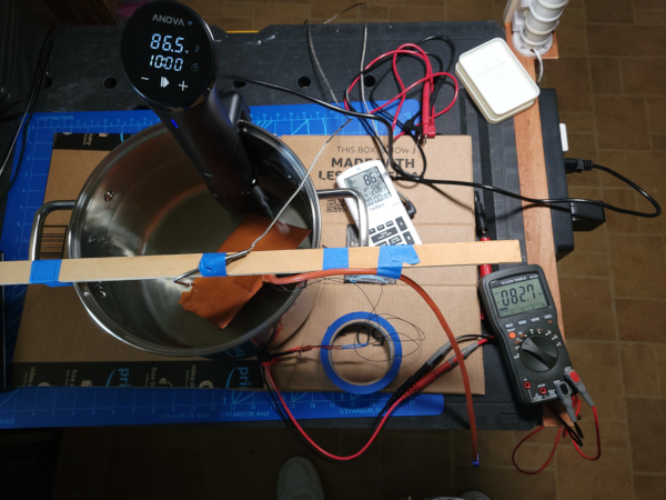
Having gathered that data, it was obvious that it was a 100K thermistor of some kind, and I found a data sheet on the web for a 100K thermistor with a table that seems to match the readings I got. So that can be the basis of the temperature detection.
Pico W
Meanwhile, I need to get the pico w talking wifi, so I've been using a little breadboard setup. I've got a 12V to 5V buck converter for power so I can use the same 12V power supply that will power the heat bed to also power the pico w [a very annoying converter that doesn't have standard pin spacing]. By using a USB cable to connect the converter to the pico w, I'll always have to unplug it from the converter if I want to program it via usb, therefore I'll never have a disaster caused by having two different 5V sources hooked up at once. Here's the current breadboard shown running off 12V::

It will probably make the most sense to print a box for all the electronics that can sit just outside the hotbox bin and run the thermistor and heatbed cable through a hole. This way the electronics don't have to be in the heat.
The biggest challenge so far was writing the code because I was betrayed by the cmake tool they insist on using for building code. The example cmake files claim to pass the environment variables for the wifi SSID and passphrase through to the compile, but they just wind up as empty strings (so it was no wonder I always got authentication errors). I changed the code to include a file with the WIFI defs, and then it worked fine.
Having gotten past that obstacle, I'm finally getting some code written:
// hotbox server to run on pico w and drive an old silicone heatbed to
// warm up a sealed bin holding filament. Very handy to have the wifi
// interface to monitor and/or set the temperature.

#include <stdio.h>

#include "pico/stdlib.h"
#include "pico/cyw43_arch.h"

#include "lwip/pbuf.h"
#include "lwip/tcp.h"

#include "hardware/adc.h"
#include "hardware/gpio.h"
#include "hardware/pwm.h"

#include "wifi_private.h"

struct client_state {
   struct tcp_pcb * client_pcb; // the pcb created during accept
   char client_ip[50]; // ascii rep of client IP addr for debug output
   u16_t client_port;  // port of client
   char inbuf[1024];
   int inbuf_len;
};

struct val_struct {
   int curval;
   int nxtval;
   float vals[3];
};

static err_t accept_hotbox_connection(void *,struct tcp_pcb *,err_t);
static err_t hotbox_sent(void *, struct tcp_pcb *, u16_t);
static err_t hotbox_recv(void *, struct tcp_pcb *, struct pbuf *, err_t);
static void hotbox_err(void *, err_t);
static void hotbox_close(void *);
static void hotbox_command(void *);
static void update_temps();
static void record_val(struct val_struct *, float);
static void set_fan_speed(int);
static bool limit_callback(struct repeating_timer *);
static void set_limit(struct tcp_pcb *, char *);
static uint32_t pwm_set_freq_duty(uint, uint, uint32_t, int);
static float lookup_temp(float);
static void set_heater(bool);

static struct tcp_pcb *server_pcb;

static struct val_struct cputemp = {0,1,{0.0,0.0,0.0}};
static struct val_struct bedtemp = {0,1,{0.0,0.0,0.0}};
static struct val_struct target = {0,1,{0.0,0.0,0.0}};

const char welcome[] = "Welcome to hotbox\n";
const char saywhat[] = "That does not compute (try typing \"help\")\n";

static unsigned long countdown = 0;
struct repeating_timer timer;
bool timer_expired = false;

static bool fan_pwm_running = false;

static bool heatbed_is_on = false;

int
main() {
    err_t err;
    struct tcp_pcb *pcb;

    // Initialize stdio to usb serial
    stdio_init_all();

    // initialize the fan to off
    gpio_init(FAN_GPIO);
    gpio_set_dir(FAN_GPIO, GPIO_OUT);
    gpio_put(FAN_GPIO, 1);

    // initialize the heatbed to off
    gpio_init(HEATBED_GPIO);
    gpio_set_dir(HEATBED_GPIO, GPIO_OUT);
    gpio_put(HEATBED_GPIO, 0);
    record_val(&target, -500.0);

    // Initialize GPIO 26 for reading thermistor
    adc_gpio_init(26);

    // Give me 5 seconds to run a terminal emulator to talk to /dev/ttyACM0
    // so I can see any debug output
    sleep_ms(5000);

    // Initialize reading of cpu internal temp
    adc_init();
    adc_set_temp_sensor_enabled(true);

    // Fill in initial values of temps
    update_temps();

   // Can't use wifi without initializing it.
   err = cyw43_arch_init();
   if (err) {
      printf("cyw43_arch_init() failed, err = %d\n",err);
      return 2;
   }

   // Light up LED to say we got initialized
   cyw43_arch_gpio_put(CYW43_WL_GPIO_LED_PIN, 1);

   // I'm not an access point, I'm a "station"
   cyw43_arch_enable_sta_mode();

   // Connect to the router
   printf("Connecting to %s...\n", WIFI_SSID);
   err = cyw43_arch_wifi_connect_timeout_ms(WIFI_SSID, WIFI_PASSWORD,
                                            CYW43_AUTH_WPA2_AES_PSK, 30000);
   if (err) {
      printf("Connection failed, err = %d\n",err);
      return 2;
   } else {
      printf("Connected.\n");
   }
   printf("IP: %s\n",
   ip4addr_ntoa(netif_ip_addr4(netif_default)));
   printf("Mask: %s\n",
   ip4addr_ntoa(netif_ip_netmask4(netif_default)));
   printf("Gateway: %s\n",
   ip4addr_ntoa(netif_ip_gw4(netif_default)));

   // Do the work to listen for connections and talk to each connectio
   // that comes in.

   pcb = tcp_new_ip_type(IPADDR_TYPE_ANY);
   if (!pcb) {
      printf("tcp_new_ip_type failed.\n");
      return 2;
   }
   err = tcp_bind(pcb, NULL, HOTBOX_PORT);
   if (err) {
      printf("failed to bind to port %u, err %d\n", HOTBOX_PORT, err);
      return 2;
   }

   // This listen call uses the port from pcb to listen on, then frees
   // the pcb, returning a new pcb (not sure why, but that's the way it is).
   server_pcb = tcp_listen_with_backlog(pcb, 1);
   if (!server_pcb) {
       printf("failed to listen\n");
       return 2;
   } else {
      // The accept_hotbox_connection callback is invoked when a new client
      // connection is made.
      tcp_accept(server_pcb, accept_hotbox_connection);
      printf("Listening on port %d\n",HOTBOX_PORT);
   }

   for ( ; ; ) {
      // Do all the periodic work in this infinite loop

      if (timer_expired) {

         // If the timer for how long to run this has expired,
         // the turn everything off

         cancel_repeating_timer(&timer);
         timer_expired = false;
         printf("The time is up.\n");
         // Turn off fans
         set_fan_speed(0);
         // Set target bed temp to absurdly low value
         record_val(&target, -500.0);
      }

      // Check all thermistor temps

      update_temps();

      // Do "bang-bang" operation of headbed

      float thermC = bedtemp.vals[bedtemp.curval];
      float targC = target.vals[target.curval];
      // Do I want to add some kind of hysteresis here?
      if (thermC > targC) {
         set_heater(false);
      } else if (thermC < targC) {
         set_heater(true);
      }

      // Do it all again in a tenth of a second

      sleep_ms(100);
   }

   // We ain't using wifi any longer.
   cyw43_arch_deinit();

   return 0;
}

// When this routine is called, it is passed a new client_pcb for the
// new client connection.
//
static err_t accept_hotbox_connection(
   void *arg,
   struct tcp_pcb *client_pcb,
   err_t err) {

   if (err != ERR_OK || client_pcb == NULL) {
      printf("Failure in accept\n");
      return err;
   }
   printf("Client connected\n");

   // Create the struct holding any information we need for each client,
   // set that as the "arg" to be passed to each callback as data comes in,
   // sent data is completed, etc.

   struct client_state * cs =
      (struct client_state*)calloc(sizeof(struct client_state),1);
   cs->client_pcb = client_pcb;

   tcp_arg(client_pcb, cs);
   tcp_sent(client_pcb, hotbox_sent);
   tcp_recv(client_pcb, hotbox_recv);
   tcp_err(client_pcb, hotbox_err);

   ip_addr_t clip;
   if (tcp_tcp_get_tcp_addrinfo(client_pcb, 0, &clip, &cs->client_port)) {
      strcpy(cs->client_ip, "unknown");
      cs->client_port = 0;
   } else {
      ipaddr_ntoa_r(&clip, cs->client_ip, sizeof(cs->client_ip));
   }
   printf("Client IP: %s, port %d\n",cs->client_ip, cs->client_port);

   err = tcp_write(client_pcb, welcome, sizeof(welcome), TCP_WRITE_FLAG_COPY);
   if (err) {
      printf("Failed to write welcome message, err = %d\n",err);
   }
   return err;
}

// This routine is called when a chunk of data has completed sending
//
static err_t hotbox_sent(void *arg, struct tcp_pcb *tpcb, u16_t len) {
//    struct client_state * cs = (struct client_state *)arg;
    // PUT CODE HERE
    printf("Completed sending %d bytes of data\n", len);
    return ERR_OK;
}

// This routine is called when a chunk of data comes in from client
//
err_t hotbox_recv(void *arg, struct tcp_pcb *tpcb, struct pbuf *p, err_t err) {
   struct client_state * cs = (struct client_state *)arg;
   if (p == NULL) {
      printf("received NULL pbuf\n");
      hotbox_close(arg);
   } else {
      // All the commands and responses should be short strings, so I'm
      // going to simplify this code by assuming I never need to collect
      // multiple chunks of pbuf (I'll fix it if experience proves me wrong).

      int len = p->tot_len;
      if (len > 0) {
         if (len >= sizeof(cs->inbuf)) {
            len = sizeof(cs->inbuf)-1;
         }
         cs->inbuf_len = pbuf_copy_partial(p, cs->inbuf, len, 0);
         cs->inbuf[len] = '\0';
      }
      // Tell library we got the data and free the pbuf we no longer need.
      tcp_recved(tpcb, p->tot_len);
      pbuf_free(p);
      hotbox_command(arg);
   }
   return ERR_OK;
}

// Called when there is an error (though I can't figure out if it
// is ever actually called, close the connection if it is called).
//
static void hotbox_err(void *arg, err_t err) {
   printf("hotbox_err %d\n", err);
   hotbox_close(arg);
}

// Close and clean up a connection
//
static void hotbox_close(void *arg) {
   err_t err;
   struct client_state * cs = (struct client_state *)arg;
   struct tcp_pcb *tpcb = cs->client_pcb;
   printf("Closing connection to client IP %s port %d\n",
          cs->client_ip, cs->client_port);
   if (tpcb != NULL) {
      tcp_arg(tpcb, NULL);
      tcp_poll(tpcb, NULL, 0);
      tcp_sent(tpcb, NULL);
      tcp_recv(tpcb, NULL);
      tcp_err(tpcb, NULL);
      err = tcp_shutdown(tpcb, 1, 1);
      if (err) {
         printf("tcp_shutdown returns err %d\n",err);
      }
      err = tcp_close(tpcb);
      if (err) {
         printf("tcp_close returns err %d\n",err);
      }
   }
   if (cs != NULL) {
      free(cs);
   }
}

// Parse the input command and execute it...
//
static void hotbox_command(void *arg) {
   err_t err = ERR_OK;
   struct client_state * cs = (struct client_state *)arg;
   struct tcp_pcb * client_pcb = cs->client_pcb;
   if (cs->inbuf_len <= 0) {
      return;
   }

   // remove line end and trailing spaces from command

   char * eol = strpbrk(cs->inbuf, "\r\n");
   if (eol != NULL) {
      *eol = '\0';
      cs->inbuf_len = eol - cs->inbuf;
   }
   while ((cs->inbuf_len > 0) && (cs->inbuf[cs->inbuf_len - 1] == ' ')) {
      cs->inbuf_len--;
   }
   cs->inbuf[cs->inbuf_len] = '\0';
   printf("Saw command: %s\n", cs->inbuf);
   if (strcmp(cs->inbuf, "bye") == 0) {
      // Simplest command terminates connection. Let's see if this works
      // before getting more complex.
      hotbox_close(arg);
   } else if (strcmp(cs->inbuf, "cputemp") == 0) {
      char answer[150];
      float tempC = cputemp.vals[cputemp.curval];
      float tempF = tempC * 9 / 5 + 32;
      sprintf(answer,"Cpu temp: %.02f C %.02f F\n",tempC,tempF);
      err = tcp_write(client_pcb, answer, strlen(answer), TCP_WRITE_FLAG_COPY);
   } else if (strcmp(cs->inbuf, "bedtemp") == 0) {
      char answer[150];
      float thermC = bedtemp.vals[bedtemp.curval];
      float thermF = thermC * 9 / 5 + 32;
      sprintf(answer,"Bed temp: %.02f C %.02f F\n", thermC, thermF);
      err = tcp_write(client_pcb, answer, strlen(answer), TCP_WRITE_FLAG_COPY);
   } else if ((strncmp(cs->inbuf, "fan", 3) == 0) && (cs->inbuf[3] == ' ')) {
      char msg[100];
      int num = atoi(&cs->inbuf[4]);
      if ((num < 0) || (num > 100)) {
         sprintf(msg, "Fan speed %d outside of range [0,100]\n", num);
         err = tcp_write(client_pcb, msg, strlen(msg), TCP_WRITE_FLAG_COPY);
      } else {
         set_fan_speed(num);
      }
   } else if ((strncmp(cs->inbuf, "limit", 5) == 0) && (cs->inbuf[5] == ' ')) {
      // limit how long the heatbed and fans will remain on
      set_limit(client_pcb, &cs->inbuf[6]);
   } else if ((strncmp(cs->inbuf, "heatbed", 7) == 0) && (cs->inbuf[7] == ' ')) {
      char answer[150];
      char * endp;
      double val = strtod(&cs->inbuf[8], &endp);
      if ((endp != NULL) && ((*endp == 'f') || (*endp == 'F'))) {
         // convert fahrenheit to celsius
         val = (val - 32.0) / (9.0/5.0);
      }
      record_val(&target, val);
      float valf = val * 9 / 5 + 32;
      sprintf(answer,"Target temp: %.02f C %.02f F\n", val, valf);
      err = tcp_write(client_pcb, answer, strlen(answer), TCP_WRITE_FLAG_COPY);
   } else if ((strncmp(cs->inbuf, "led", 3) == 0) && (cs->inbuf[3] == ' ')) {
      if (strcmp(&cs->inbuf[4], "on") == 0) {
         cyw43_arch_gpio_put(CYW43_WL_GPIO_LED_PIN, 1);
      } else if (strcmp(&cs->inbuf[4], "off") == 0) {
         cyw43_arch_gpio_put(CYW43_WL_GPIO_LED_PIN, 0);
      } else {
         char msg[100];
         sprintf(msg, "Unrecognized \"%s\", arg should be \"on\" or \"off\"\n",
                 &cs->inbuf[4]);
         err = tcp_write(client_pcb, msg, strlen(msg), TCP_WRITE_FLAG_COPY);
      }
   } else if (strcmp(cs->inbuf, "help") == 0) {
      const char helpmsg[] = "\
bye       close connection\n\
cputemp   print internal cpu temp of pico\n\
bedtemp   print heatbed temp\n\
fan       set fan speed [0,100]\n\
limit     set how long heater and fan will run (numbers with h m or s suffix)\n\
heatbed   set heatbed target temp (numbers with f or c suffix)\n\
led       turn led on or off\n\
help      print this help\n";
      err = tcp_write(client_pcb, helpmsg, strlen(helpmsg), TCP_WRITE_FLAG_COPY);
   } else {
      // Unrecognized command
      err = tcp_write(client_pcb, saywhat, sizeof(saywhat), TCP_WRITE_FLAG_COPY);
   }
   if (err) {
      printf("Command %s err %d\n",cs->inbuf,err);
   }
}

static void set_limit(struct tcp_pcb * client_pcb, char * args) {
   // Parse the arguments to the limit command and start (or stop) the timer
   if (strncmp(args, "off", 3) == 0) {
      // Turn off the timer if it is running
      static const char msg[] = "Heatbed and fans will never be turned off.\n";
      if (countdown > 0) {
         cancel_repeating_timer(&timer);
         countdown = 0;
         timer_expired = false;
      }
      tcp_write(client_pcb, msg, strlen(msg), TCP_WRITE_FLAG_COPY);
   } else {
      // Any collection of numbers with h m or s suffix chars are added
      // up to create the value for total seconds to set the limit
      bool garbage = false;
      double tot_sec = 0.0;
      while ((! garbage) && (*args != '\0')) {
         char * endp;
         double val = strtod(args, &endp);
         if (args == endp) {
            // Woa! Didn't advance, must be garbage on line.
            char msg[100];
            sprintf(msg,"Do not recognize %s\n",args);
            tcp_write(client_pcb, msg, strlen(msg), TCP_WRITE_FLAG_COPY);
            garbage = true;
            break;
         }
         double mult = 1.0;
         args = endp;
         switch(*endp) {
            case 'H': case 'h':
               mult = 60.0 * 60.0;
               args++;
               break;
            case 'M': case 'm':
               mult = 60.0;
               args++;
               break;
            case 'S': case 's':
               mult = 1.0;
               args++;
               break;
         }
         tot_sec += (val * mult);
      }
      if (! garbage) {
         if (countdown > 0) {
            // If a previous limit timer is running, cancel it
            cancel_repeating_timer(&timer);
         }
         countdown = (unsigned long)tot_sec;
         char msg[100];
         sprintf(msg,"Heatbed and fans will be turned off in %lu seconds.\n",
                 countdown);
         add_repeating_timer_ms(1000, limit_callback, NULL, &timer);
         tcp_write(client_pcb, msg, strlen(msg), TCP_WRITE_FLAG_COPY);
      }
   }
}

static bool limit_callback(struct repeating_timer *t) {
   if (countdown > 0) {
      countdown--;
      if (countdown == 0) {
         timer_expired = true;
      }
   }
   return true;
}

static void set_fan_speed(int num) {
   if ((num == 0) || (num == 100)) {
      if (fan_pwm_running) {
         // If I want full on or full off, get FAN_GPIO completely out
         // of pwm mode
         pwm_set_enabled(pwm_gpio_to_slice_num(FAN_GPIO), false);
         fan_pwm_running = false;
         gpio_init(FAN_GPIO);
         gpio_set_dir(FAN_GPIO, GPIO_OUT);
      }
      if (num == 0) {
         gpio_put(FAN_GPIO, 1);
      } else {
         gpio_put(FAN_GPIO, 0);
      }
   } else {
      // For a fractional fan speed, go back to PWM mode if we aren't
      // already.
      if (! fan_pwm_running) {
         gpio_set_function(FAN_GPIO, GPIO_FUNC_PWM);
      }
      pwm_set_freq_duty(pwm_gpio_to_slice_num(FAN_GPIO),
                        pwm_gpio_to_channel(FAN_GPIO),
                        1000,
                        100 - num);
      pwm_set_enabled(pwm_gpio_to_slice_num(FAN_GPIO), true);
      fan_pwm_running = true;
   }
}

// Handy utility function stolen from The Pico In C: Basic PWM by Harry Fairhead
//
static uint32_t pwm_set_freq_duty(uint slice_num,
                                  uint chan,
                                  uint32_t f,
                                  int d)
{
   uint32_t clock = 125000000;
   uint32_t divider16 = clock / f / 4096 +
                             (clock % (f * 4096) != 0);
   if (divider16 / 16 == 0)
   divider16 = 16;
   uint32_t wrap = clock * 16 / divider16 / f - 1;
   pwm_set_clkdiv_int_frac(slice_num, divider16/16,
                                       divider16 & 0xF);
   pwm_set_wrap(slice_num, wrap);
   pwm_set_chan_level(slice_num, chan, wrap * d / 100);
   return wrap;
}

static void update_temps() {
   // Steal this code from pico-examples/adc/adc_console/adc_console.c
   // to get the internal CPU temperature.

   // 12-bit conversion, assume max value == ADC_VREF == 3.3 V
   const float conversionFactor = 3.3f / (1 << 12);

   // Read the internal chip temp
   adc_select_input(4);
   float adc = (float)adc_read() * conversionFactor;
   float tempC = 27.0f - (adc - 0.706f) / 0.001721f;

   // read the voltage from the thermistor voltage divider
   // PUT CODE HERE - figure out how to convert resistance to temperature...

   adc_select_input(0);
   float thermv = conversionFactor * adc_read();
   float thermr = (thermv*THERMISTOR_R0)/(3.3-thermv);
   float thermC = lookup_temp(thermr);

   record_val(&cputemp, tempC);
   record_val(&bedtemp, thermC);
}

static void set_heater(bool onoff) {
   if (onoff) {
      // I want to turn heatbed on if it isn't already on
      if (! heatbed_is_on) {
         printf("Turning heatbed on.\n");
         gpio_put(HEATBED_GPIO, 1);
         heatbed_is_on = true;
      }
   } else {
      // I want to turn heatbed off if it isn't already off
      if (heatbed_is_on) {
         printf("Turning heatbed off.\n");
         gpio_put(HEATBED_GPIO, 0);
         heatbed_is_on = false;
      }
   }
}

static void record_val(struct val_struct * vs, float newval) {
   int nxt = vs->nxtval++;
   if (nxt >= 3) {
      nxt = 0;
      vs->nxtval = nxt;
   }
   vs->vals[nxt] = newval;
   vs->curval = nxt;
}

#include "thermistor.h"

static float lookup_temp(float thermr) {
   // The pico has nothing better to do than spin most of the time
   // so don't go all insane and try to code a broken binary search
   // here, just linear search the thermistor table.

   int i;
   for (i = 0; i < THERM_LOOKUP_NUM-1; ++i) {
      if ((therm_lookup[i].ohms >= thermr) &&
          (therm_lookup[i+1].ohms < thermr)) {
         // OK, the resistance we have lies between i and i+1, figure
         // out the percentage between the entries and apply that to
         // the temp to get the return value.
         float ediff = therm_lookup[i].ohms - therm_lookup[i+1].ohms;
         float rdiff = therm_lookup[i].ohms - thermr;
         float tdiff = therm_lookup[i+1].tempC - therm_lookup[i].tempC;
         return therm_lookup[i].tempC + (tdiff * (rdiff / ediff));
      }
   }
   // Something is seriously wrong if I get here, so return a seriously
   // wrong value.
   return 0.0;
}
I think I have almost everything working except the heatbed. I'm waiting for some electronics to drive the fans (but tested the PWM output by dimming an LED rather than slowing a fan). I've done everything with just USB power so far, but I'll need to get the 12V power supply involved next (which takes more room, so I'll have to figure out where to test everything).
The breadboard has gotten more complex:

Plastic Bin
This IRIS USA 62.8 Quart WEATHERPRO Plastic Storage Box set was on sale, so that's why I selected this size :-).
Both of them fit on the bottom shelf (but I'm only working on one of them right now):

I made a plywood and conduit insert with two levels of spool storage (one has to be higher than the other so they fit). A cardboard template allowed me to figure out where to put the rods to support normal size spool and still allow the lid to close. Looks like I can fit 6 spools on each level:

I 3D printed some little plugs to fit outside the ends of the conduit to keep them from sliding out of the holes. I suppose I could have glued them in place, but gaffer tape was quicker and easier :-). Once the structure is in the box, the end panels have nowhere to go, so everything stays together quite well.
I've got plenty of space under the top level to put the heat bed and a fan or two to circulate the air. I'll have to drill holes to run the cables, but that can wait till I get all the electronics and software working and I know exactly what I need.
I've been cobbling up some stuff to go inside the bin. Here is a little circuit board with fan headers to distribute power to up to four radial fans (they all work in this test with 12V power connected). Eventually, I'll be sending the PWM modulated signal to them for speed control, but I'm waiting on some electronics to breadboard up a fan driver circuit.

Probably no need to include all 4 fans in the hotbox, but since I had 4 of them, I figured I might as well test all of them.
I've now temporarily stuck my terminal blocks and SSR on a scrap of MDF I had laying around so I could get the SSR wired up to control the heatbed:

Just need to pick a pin to control the SSR and fill in the code.
Meanwhile, my transistors and mosfets arrived, and it was too cramped to try and test the circuit on the original breadboard, so I used a small breadboard just for the fan control so I could see what I was doing. I also used a different pico w with a better 5V converter (it fits in normal pin spacing properly):

This implements the example circuit from the digikey website. Once I got everything hooked up correctly, it works fine. I was surprised at how much I could reduce the fan speed without the fan stalling.
Added the code to run the SSR to turn the heatbed on and off, and everything seems to work with the spaghetti breadboard:

The crude "bang-bang" control for the heatbed seems to work well. I can watch the SSR led turn on and off as it regulates the heat. The fan still works after adding the new jumpers for the heater (so I avoided unplugging anything). The next challenge will be seeing how I can best cram everything onto a soldered breadboard...
Soldering
I'm now soldering everything to a breadboard, and it turns out Play-Doh is useful:

I need to solder on a few two pin headers where external cables will plug in, so there isn't enough header to grab. A couple of pea size blobs of Play-Doh squished on either side of the header does a pretty good job holding it straight while I flip it over and solder the other side :-).
Where there is room, blue painters tape is also handy for sticking down larger things while soldering.
I have finished soldering on all the components (only screwed up one thing by initially soldering in the transistor backwards :-), but everything now works and it is a lot neater than the mess of jumpers on the breadboard:

Here's a closer look at the finished board with the various headers described:

Enclosure
I've designed a fairly complex box in OpenSCAD with a gazillion embedded nuts for mounting things and screwing the box halves together. My first attempt at printing it did not go well. I need to reverse a bunch of changes I made in the slicer and then print some test pieces to see if the embedded nuts work properly (the first attempt didn't leave enough slop).
I've printed a test piece this time instead of the full size box, and it worked better now that I adjusted the slop to leave a tad more room for the nuts. Perhaps I should add another 0.1mm to the height for the M4 nut as it was a little tight. I'm still not getting really good prints though. I need to look at the calibration of more stuff to see if I can eradicate the gaps it seems to leave between walls. At least the depth of all the nuts and holes seem good. I can secure each of the components to their corresponding test print support using the metric screws without hitting the bottom of the screw hole while still solidly securing the component.
Things to do: Check filament diameter. Calibrate extruder steps. Single wall print to measure line width and adjust with flow rate (copy profile to adjust for single wall while making sure all other settings stay the same). Might be a good time to make sure all the bolts are tight as well.
I did all that, and found a bunch of things to adjust in the settings, but I still get the thing with outer walls of small diameter curves not meeting.
I should configure Prusa Slicer to work with Jiggit and see if the same defects show up. Hey! The print is perfect with Prusa Slicer! I wonder what settings are different? [Actually it it isn't perfect - I see different defects looking closer on the base instead of the top.]
I guess the next step is to compare the settings in detail to see what is different. I know the speed is faster with prusa, and I think the prusa default is 3 perimiters rather than 2, perhaps change things 1 at a time and see if it gets better...
While these ideas have been fermenting, my Prusa MK4 kit arrived, and I should be able to print the case on it with better results. I've also decided to use heatset insert for the parts that need threads since they are less finicky to use than embedding nuts.
I printed a test block, found that the M3 inserts wouldn't fit in the first test block, so printed another one:

With my sealed bin of five filament spools it is really easy to change filament, so I couldn't resist making the test blocks a bit fancy :-).
By coincidence, the silicone socks I ordered for the print head arrived the same day, so I swapped in the satin sheet print bed, installed the sock, and tried printing a PETG test. Seemed to work fine, so maybe the box is next...
After a few test prints to get the size holes for the heatset inserts exactly right, the box bottom half is printing (over 3 hours, so that will be the longest print I've done so far).
The long print worked. The MK4 did a wonderful job, much less stringing than PETG on my home built monster:

The satin print sheet is also great. I don't even have to take it off the bed and flex it, PETG just comes right off once it cools down to room temp.
Now have the box top printing (a little less than 3 hours without so many complex features).
Meanwhile, I got the inserts installed. It was very easy, the biggest pain was waiting for the soldering iron to cool down to switch to a different size tip:

After the inserts cooled down, I could install the components, and they all fit nicely:

The top finished printing and I was able to install it and see how all the various openings work. The cords that output power to the heatbed fit in the provided holes (still need to build the cables for the thermistor and fans):

The 12V power input works in the socket nicely:

The hole for the usb port isn't centered exactly correctly, but a usb cable still fits in the connector if I need to program the pico:

Now I've started making the remaining cables I need, and it has been an adventure :-). I ordered some tiny wire sleeving that is a good size for my cables, but getting the wires fed through the sleeve is the adventure. I finally worked out the following procedure:
- Strip insulation from a length of 14 gauge solid copper wire.
- Straighten it out by clamping one end and spinning other end in drill.
- Spread CA glue on one end and wrap lots of turns of thread around it to secure the thread.
- The wire is stiff enough to push through a length of the sleeve.
- That drags the thread after it.
- After the thread is through, tie the end to some very flexible 28 gauge wire and pull the wire through.
- Now you can solder the wires you really want in the sleeve to the end of the 28 gauge wire and pull them through.
- At long last, you have the cable you want. Clip the frayed end of the sleeve so you can slide some heat shrink tubing on, crimp connectors on the ends, secure the heat shrink over the ends of the sleeve, and Bob's your uncle.
- Whew!
The first cable I did was the thermistor cable on the heat bed (previously was just two small wires with no protection):

I'm using JST inline connectors for the ends of the thermistor and fan cables since I had some laying around. I'll use different genders on the thermisor and fan ends so I can't get them confused.
Next step was getting things mounted to the plywood everything in the box will be attached to. First mount the circuit board that distributes power to the fans:

For some reason, I messed up this mount more ways than I can remember (wrong dimensions, wrong hole sizes, etc), but I finally got it right, and the board secured to it:

Next, added a cable clamp to hold down all the cables securely:

Then added mounts for two radial fans:

And installed the fans:

The fans are intended to suck up hot air rising off the heater and blow it in two different directions to get the box evenly heated. That completes the part that will go inside the hotbox.
Seemed like a good idea to test that it does indeed fit in the bin with the spool rack installed:

It fits under the upper rack and doesn't collide with the spools. I'll need to drill some holes in the rack (as well as making holes in the bin) to get the cables out, but that's for later...
I got the thermistor cable built which let me test it and the heatbed, and it all works (whew!).
I've built the fan cable as well, and installed it:

With everything plugged together, I'm ready to test:

I didn't break anything! It all works! Screenshot from phone as proof:

Checked the heater temp with my IR thermometer, and it hung around 40C as requested (a little hotter as I didn't try to calibrate the thermistor very exactly, for that matter I have no idea how accurate the IR thermometer is).
Now I need to (very carefully) make holes in the bin and get it installed...
There isn't any room to work inside the bin once the rack is in place and the rack needs to be in place before I can run the cables through any holes, so I need a design for the seal around the exiting cables that can be installed completely from the outside after I install whatever inside part it connects to. I'll have to think about what I want to build for a bit...
I've come up with this design:

I can bolt the back piece to the inside of the bin (after making appropriate holes) then run the cables through the hole, clamp the two cable clamp pieces down to the cables and insert the wedge shape into the back piece, then run the cables through the front piece and insert the other half of the cable clamp in it. The front piece has large holes on the side to clear the M3 bolt caps and it is then secured with the top and bottom screws. The result is cables held securely and very little path for nasty outside humidity to enter the bin.
I've also printed a template to help drill the holes for the bolts and cut out the larger center hole. The model depends on the wall thickness of the bin, and I should be able to measure that once I get the hole cut.
A test print of the pieces has given promsing results. I'll probably still want some tweaks before printing the final version. Since the heat set inserts worked so well on the box, I'll use them on this as well.
I used the template to drill lots of holes (seemed to be very handy for that):

Then worked on the inside hole with an xacto and dremel to smooth the bumpy edges once I got the plastic out. Sanding stick was also involved. Not the most beautiful hole, but seems to be big enough, which is the most important part:

I put the rack back in the bin so I could draw on the plywood where I need a matching hole. To the drill press! I'm also printing the (hopefully) final versions of the parts now that I know the bin thickness.
Got the hole in the plywood drilled out, added 3mm heat set inserts to the inside part of the cable holder and mounted it in the bin. Added the rack, added the heatbed platform, ran the cables through the side and attached the outside parts of the cable holder:

Inside the bin, you can see the cables going though the plywood and the side of the bin:

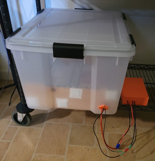
The bin fits on the shelf with the controller beside it:
I verified that everything still works properly. I'll probably want to do something like velcro the controller to the side of the bin to make it easier to move them both together. I also want to put a hole in the top of the bin to mount the humidity sensor (hopefully I can clamp it on the drill press and use the 42mm forstner bit more successfully than I did last time :-).
Tried to drill a 42mm hole in the bin top. It did not go well even with the top securely clamped to drill press:

Fortunately, a 3D printer can fix that :-). Print a flat patch and install sensor through it. Draw the shape of the big chip in the side. Take it off, run it through a scanner, use gimp to outline the chip, convert that selection to a path and then to an svg file, import that svg into OpenSCAD, extrude the chip shape to thickness of bin top, print final version of patch. Simple!

Now I can find out if the little bitty heat bed can raise the temperature in the whole bin (and how long it takes).
References
"Programming The Raspberry Pi Pico/W In C, Second Edition" by Harry Fairhead is a handy book which decrypts a lot of the SDK so you don't have to strain your brain interpreting SDK documentation and trying to decide how it applies to what you are trying to accomplish. The utility function for setting PWM frequency and duty cycle was particulary useful, since that isn't something you can do obviously via the provided SDK interfaces.
The example circuit from the digikey web site worked great for controlling fan speed.
This video about providing power to a pico showed me the correct way to insert a schottky diode between the 5V converter and the VSYS pin to avoid problems if you happen to plug in the USB while also powering the pico from an external source. [I think that's unlikely to happen, but it was trivial to add for insurance.]
The JuiceSSH android app is handy for talking telnet to the pico w via my phone when I'm not near a computer, and is the simplest way to test this with everything plugged in.