Extruder
While I'm having fun with openscad building my new printer, I figured I might as well design an extruder as well. I wanted it to mount to the V-slot rail and I also wanted the PTFE tubing to run all the way to the hobbed gear (both coming in and going out) so that there would be no way the filament could go anywhere except between the hobbed gear and the bearing. I also like the idea of feeding the filament through the tube from a sealed box with dessicant so it is exposed to the environment only in the few millimeters in the center of the extruder. Heck, maybe it will also work with flexible filament.
How well this all winds up working remains to be seen, but I did manage to print and build one. All the openscad for the parts is included in the tarball on the openscad page.
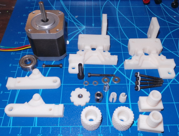
Here are all the parts ready to go:
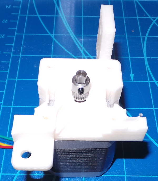
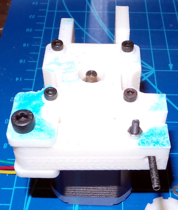
Step 1: Place extruder_body_one on the motor, secure the hobbed gear (I'm using a HobbGoblin from E3D, but you could change the hole size for a different gear in the openscad source, but that would also probably cascade to adjusting the offset of the 4mm channel, etc.) so the center of the hobb is level with the top of the first part.
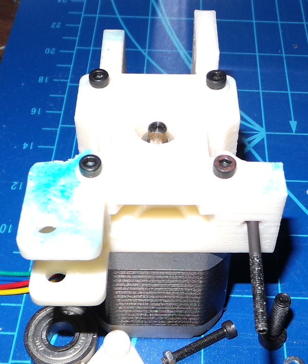
Step 2: Put extruder_body_two on top, including a 30mm M3 bolt in the hole where it will be captured between the parts. This will eventually hold the spring that compresses the lever arm. A longer bolt and a bigger spring might be better, but this was the spring I found in my junk pile. Put the 4 screw_spacer pieces on 4 30mm M3 bolts and screw down both halves of the extruder body to the nema 17 motor.
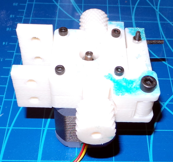
Step 3: Assemble the lever arm by putting the skate bearing on the 8mm posts and pushing both arm halves together to trap the bearing (a lot of filing and sanding was actually required to make this fit well - I probably want to adjust the dimensions a bit if I print a new one). A short M3 screw makes sure the two halves of the arm are secure (I think I used an 20mm screw but a shorter one might be better). Push the arm into the extruder so the M5 hole line up at the bottom and the M3 screw runs through the hole at the top. Add an M5 bolt as a fulcrum for the lever arm (a 30mm bolt and a lock nut would be ideal, but I just have a shorter bolt for testing at the moment).
Step 4: Push the bowden_threaded_adapter parts into the matching holes. Be sure the end of the adapter with the bump on it is forced down flush with the face of the motor. (These were really tight and also required a bit of filing before I could force them into place, but that is probably a good thing). If everything printed correctly, the holes in these adapters will line up exactly with the 4mm channel in the extruder bodies.
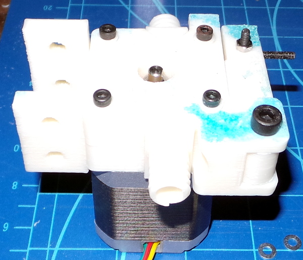
Step 5: I'm not installing any PTFE tubing yet, but if I did, I'd cut the end to a pointy shape to fit as close as possible to the gear, shove the bowden_cap part over the tube, followed by the cone shaped bowden_ring part then shove the tube down into the extruder to just before the gear and tighten the cap over the cone to squeeze the tube and secure it in place. Here I've just put on the cones and caps so I won't lose them.
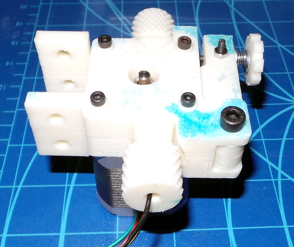
Step 6: Small washer, large washer, spring, large washer, small washer, tension_nut all go on the 30mm bolt to force the skate bearing against the filament. Make sure you put the M3 nut on the outside so the spring will force the disk against the nut and everything won't fall apart. If I find a stronger spring I may want to use a 35mm bolt here. I ran a scrap of filament into the extruder and turned the shaft with some needle nosed pliers, and it did indeed drag the filament into the extruder, so the first and simplest test works.
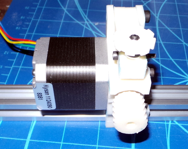
Step 7: Here you see how the tabs on the extruder will fit on a V-slot rail with some T-nuts to secure it in place (and probably a wire tie around the motor as well).