Building
FYI: All the 3D printed parts mentioned in here can be found over in the Openscad Parts page.
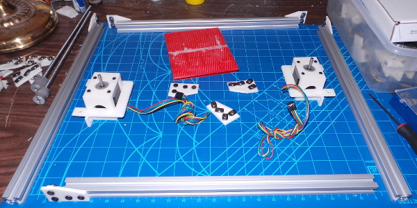
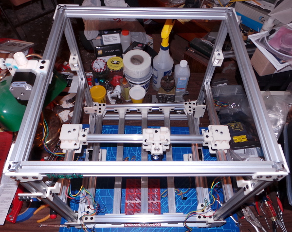
I've got enough stuff collected now to start trying to actually build this thing:
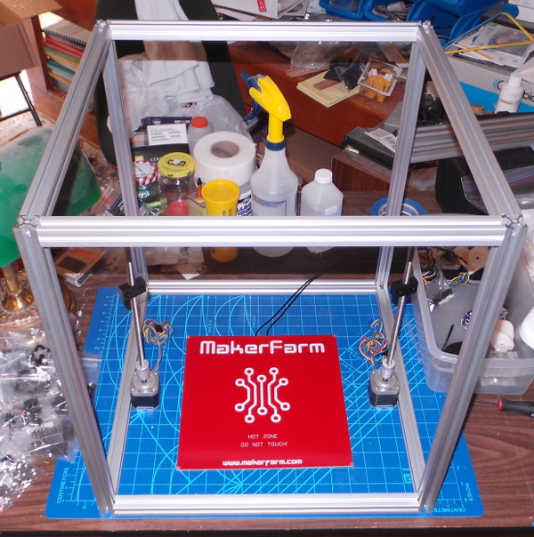
Here you see the first test assembly of the frame with the heads of low profile 10mm M5 screws slid into the slots on the verticals and the ends of the horizontal pieces threaded to be secured with the screws. (Holes drilled 10mm in to the vertical allows a socket driver to tighten the screws). I also had to use a washer on each screw since the threads on the low profile screws don't go all the way up.
This looks pretty good and is quite stiff, but didn't come out as square as I would have liked. The horizontal pieces are all ordinary t-slot extrusions I had pre-cut by Misumi, and I guess the ends aren't cut square enough to be able to use this assembly technique. I'll probably have to print some corner plates instead (or figure out how to square off the ends perfectly).
In case you wonder about scale, the heat bed shown is 10 inches square.
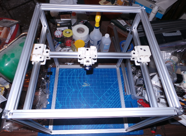
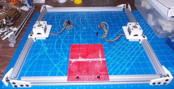
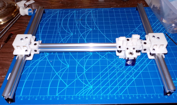
Now I've added the X and Y rails (cut from v-slot extrusions) and included the previously printed carriages. Everything seems to move quite smoothly when I drag it around by hand, so any slight lack of squarness in the frame doesn't seem to be a problem for X and Y motion (but I suspect it will be an issue for Z because I want the build platform to ride up and down on the vertical rails, so they will need to be very parallel).
I guess the next thing is adding the motor and idler pulley mounts and trying to hook everything up and test X and Y motion...
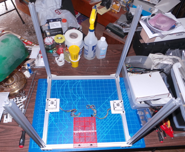
But first! I printed a slew of corner plates and rebuilt (most of) the frame:
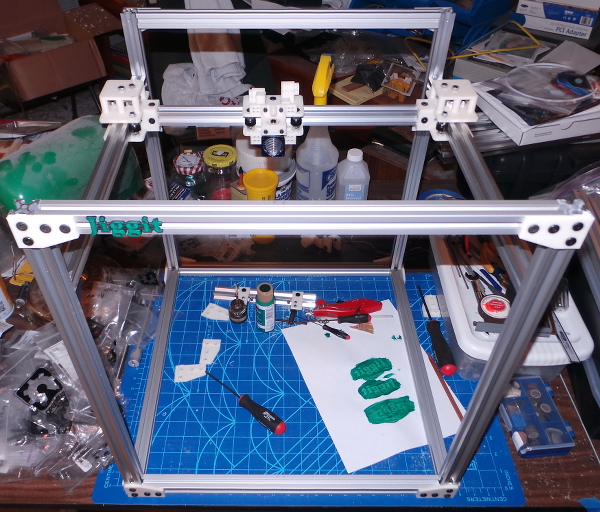
While I was printing corner plates, I redesigned the nameplate to fit a t-slot and I've added it as well. I've now run out of 10mm low profile M5 screws and t-nuts though, so I'll need to get more of them before I can get everything back together.
The corner plates give me a nice square frame. I was able to measure the diagonals and also use a square when putting together the front pieces and everything reads as square. Then when putting together the back, I loosened all the screws, and positioned all the pieces to exactly match the front before tightening the screws, so everything matches and there is no more rocking when it sits on a flat surface.
I've got a lot of small gauge hookup wire on order to make cables for all the limit switches. I'll definitely want to verify they all work before I try to run the motors :-).
Before I get into building the printer itself, I put together the power supply cover, adding a switch and a socket for an A/C cable I salvaged from an old dead computer power supply. The parts used here are the cover itself, power_cover.scad and 3 of power_brackets.scad. The power supply I'm using has several M4 screw holes for mounting, and I used 3 M4 8mm socket cap screws to mount the brackets (which were glued to the cover with acetone). The A/C socket needed 3/8" 4-40 phillips flat head screws which were secured on the inside with 4-40 lock nuts. The switch snaps in place (something you don't want to do very much or it will strip the narrow printed edge of the hole it snaps into). Here's the inside shot:
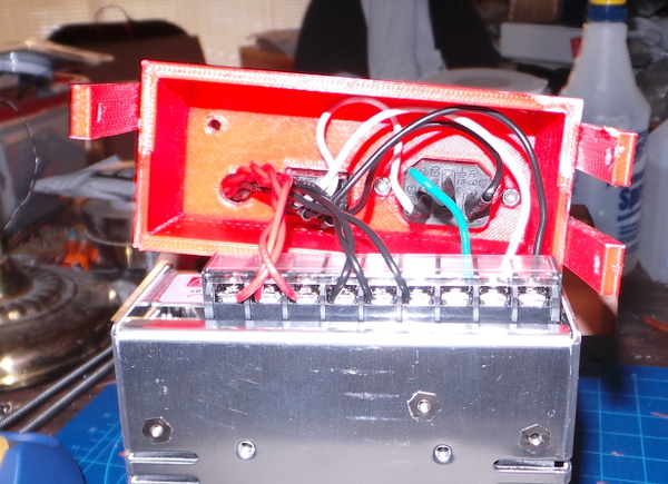
And the assembled cover and power supply:
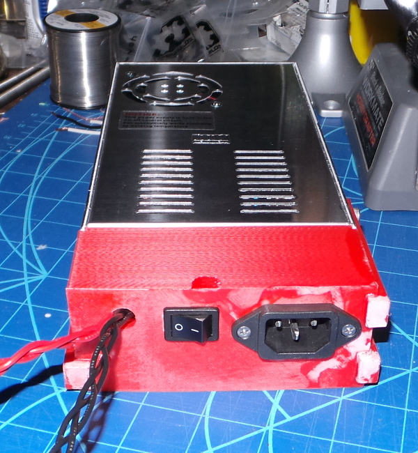
Not a very elegant appearance, but it seems to work OK. The 12V cables coming out of the hole are 18 gauge and will be terminated with a high amperage EC3 style connector (used a lot in radio control equipment).
I could claim I'm printing all the electrical parts in red, but really I just ran out of natural color filament :-).
This has all just been putting things together for testing, but everything that slides into one of the rails needs to be in place before I put the corner plates on and make it impossible to slide in anything new, so I've been working on a build procedure I hope will let me put everything together without discovering I need to take it apart to add something.
The maroon bits below still need to be figured out before I can really start final assembly:
Bottom parts
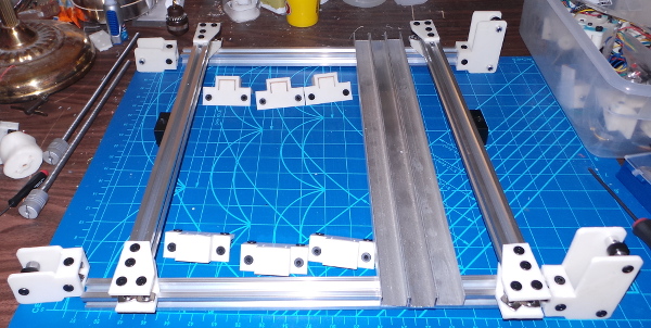
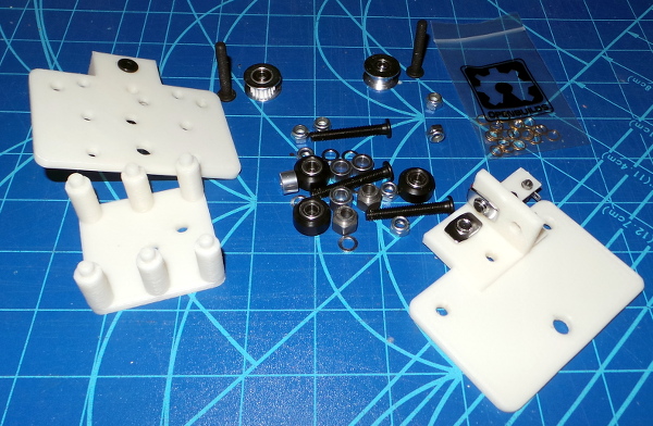
This will need 4 of the corner-plate.scad parts (two mirror image plates generated by the scad file for a total of 8 corner plates). Each corner plate needs 4 10mm low profile M5 screws and 4 T-nuts. The smoothieboard mount is in 2 parts, smoothie-near.scad and smoothie-far.scad. These attach to each other with a couple of 6mm M3 socket cap screws and M3 nuts, then are welded with some acetone around the seam for additional strength. Another 4 10mm screws and T-nuts hold it on the front rail. The two stepper motors (which will provide Z motion) are attached to the side rails with the z_motor_cap.scad and the z_motor_horizontal.scad parts. The motor is screwed into the cap with 4 6mm M3 socket cap screws, and another 4 10mm M5 screws and T-nuts secure the motor mounts to the rails. Here are the parts laid out for assembly:
Start with front bottom rail.
Attach the smoothieboard mount.
Note: If I want to mount the power supply, I'll probably need to do that here as well, but at the moment I'm thinking the supply just sits outside the frame somewhere with a cable and plug running to the smoothieboard. The mount has lots of spare M3 size holes on the side for use later to attach things like a mosfet for driving the print bed heater, extra 12V headers for lights and fans, etc.
On the side bottom rails:
Slide on the Z motors.
On all the bottom rails:
Slide on the corner plates. That completes the assembly of the bottom pieces:
Setup vertical rails
Slide the vertical rails into the corner plates and join everything as close to perfectly square as possible. (This gets tricky with all the junk attached to the rails - hard to measure diagonals - I'll probably have to fiddle with this a lot as the build proceeds.)
On the front left vertical rail:
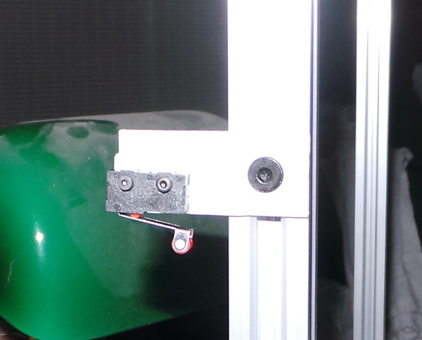
Slide on the Z limit switch facing up to contact the print bed carriage when it gets too low (don't want to smash into the motor assemblies).
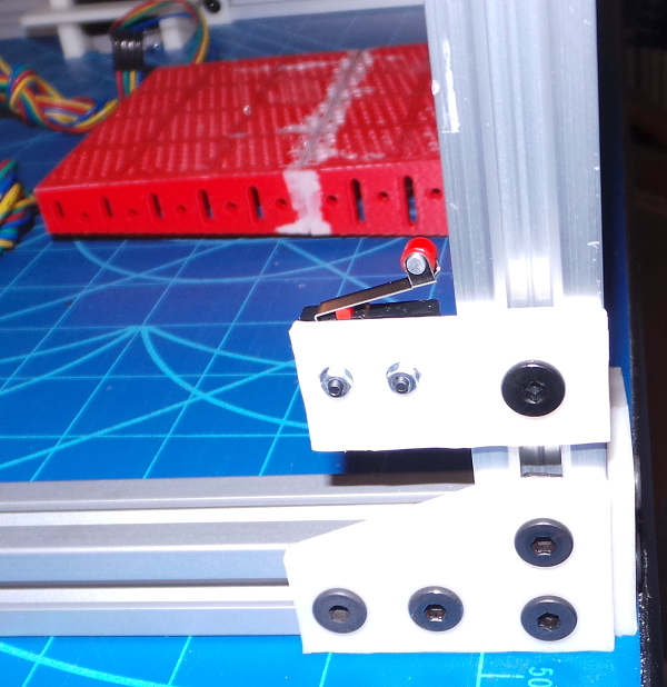
The switch mount is from zstop.scad (which also includes the top parts we'll add later). Since this is a thinner part, it needs an 8mm M5 screw (the 10mm is too long and runs into the rail before it secures the T-nut). The microswitch is attached with 2 12mm M2 socket cap screws, nuts, and washers. (P.S. In the background you can see the M3 holes in the side of the smoothieboard mount where additional junk can be mounted).
Build the print bed structure
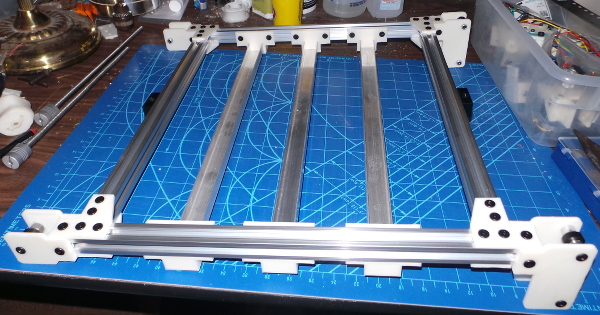
Here are the partially assembled parts for the print bed (or the frame to hold it - the actual bed will come later):
There are 6 of the bedbracket.scad parts to hold lengths of 3/4" aluminum C channel (channel facing up) under the frame. Each of the brackets takes 4 10mm M5 screws and 4 T-nuts to hold it to the rail. I used superglue on one end of the aluminum channels and allow the other end to slide in the btracket so the width can be adjusted to match the vertical rails. There are also 4 of the vv-corner-plate.scad parts printed for a total of 8 corner plates to hold the cross bar rails in place. Each of the plates takes another 4 10mm M5 screws and 4 T-nuts. The cross bars also hold the openbuilds acme screw nut blocks attached with 2 15mm M5 screws and T-nuts. The ends of the rails ride on openbuilds mini V-wheels with two wheels on the right side and one wheel on the left. The wheels are all attached with 1/4" aluminum spacers and 35mm low profile M5 screws with M5 lock nuts. The single wheel carriage part is z1.scad (print a total of 4), and the two wheel carriage parts are z2-top.scad and z2-bottom.scad. Print two each of them.
I previously cut some aluminum rails with a hacksaw. That led me to search for a better way, which turned out to be this Diablo table saw blade. It cuts aluminum smooth as silk and is infinitely less work than a hacksaw. I used it to cut the V-slot rails and aluminum channels for the print bed frame.
In the middle of the front and back rails, slide on 3 each of the brackets to hold lengths of aluminum C channel (channel facing up). These will provide a place to secure the nuts for the bed leveling screws and springs (which can be drilled later when I know exactly where they need to go, no doubt using a special 3D printed jig to get the holes lines up perfectly with the bed itself).
On the outside of the left and right rails, slide the Z nut blocks.
Attach the corner plates to the left and right rails, slide onto the front and back rails.
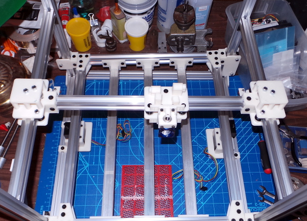
Attach the wheels and support brackets to the left and right ends of the front and back rails. That gives me an assembled print bed frame:
Slide the entire print bed down over the vertical rails.
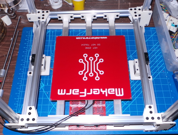
This will need a lot of tweaking to adjust the positions of the Z motors, rails, nut blocks, etc., but you can see how it will fit. I have high hopes that once the motors and nut blocks are aligned and the weight of the platform is supported by the acme screws that the small number of wheels will provide adequate stabilization. If not, I guess I'll be taking things apart one more time to add beefier vertical carriages :-).
Z stop
Slide the Z-stop switch assembly over whichever front rail seems to work best. Glue the M3 adjusting screw holder on the print bed wheel bracket so the screw will connect with the switch. (Just thinking about it, I suspect I should delay gluing on the adjusting screw holder till I'm sure I have all the parts lined up in their final positions).
By putting the Z stop switch on the outside of the front left rail, I'll be able to move it up beyond the X-Y assembly if I need to, and the Z adjusting screw will be accessible directly on the front of the printer. This part is also printed by the zstop.scad file.
Interlude with washers...
I'm slowly building up my collection of spacers I'll need to put between stacked pulleys so they can turn smoothly in opposite directions. This is a pain because the only source I've been able to come up with for spacers that work well is to make them myself by drilling 5mm holes in 7mm diameter brass M3 washers.
I tried various way to hold the washers for drilling, but finally came up with a scheme that works fairly well:
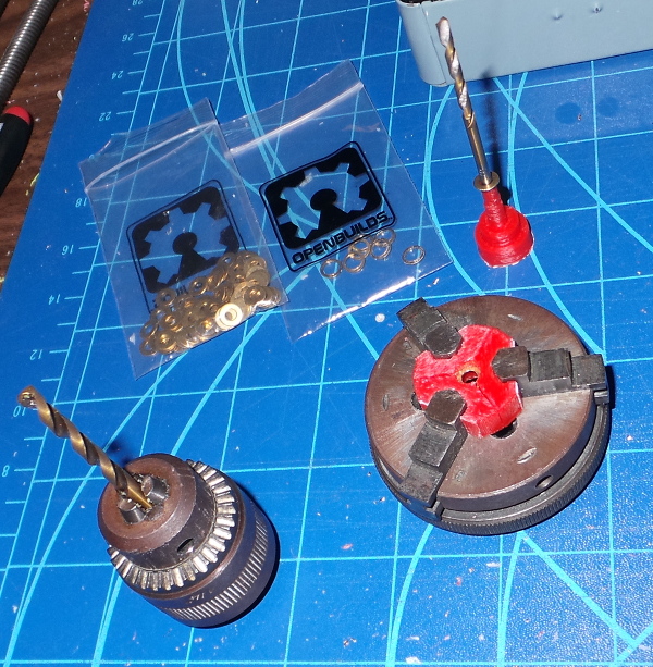
I fitted out my ancient ultimat mini-lathe chuck with some printed plastic jaws that have a tiny groove for grabbing the washer. Another printed plastic support holds the washers (centered on a 3mm drill bit) at just the right height when the chuck is placed over the holder so the washer will be grabbed in the groove when I close the chuck.
This holds things well enough that I can use the drill chuck as a hand drill and work my way up in 0.1mm increments from a 3.5mm drill bit to a 5mm drill bit, increasing the hole size each time.
Now I just need to make enough that I'll be able to put together all the parts that need pulley spacers...
BBZZZZTTT! That doesn't work either, not for long. Plastic just can't hold the little washers reliably enough. Time for the metal solution:
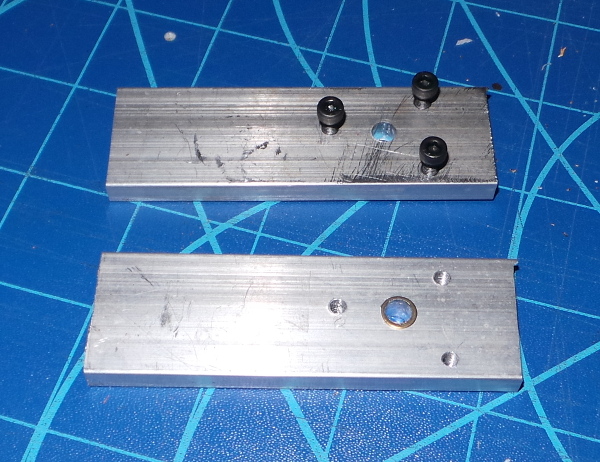
This is a custom vice just for the washers I made from a couple of pieces of aluminum bar stock. I drilled 3 2.5mm holes near one end in a triangle, tapped one side for M3 screws and drilled out the other side to 3mm. Then after securing the pieces together with M3 screws, I drilled a 5mm hole in the center of the triangle.
Now I can put a washer over the 5mm hole, put the two aluminum pieces together and screw in the M3 screws loosely. Rotate the 5mm drill bit back and forth in the hole a few times, and the conical tip of the drill bit centers the hole in the washer pretty well, then I can crank down the M3 screws as hard as I can get them and proceed to drill out the center of the washer with the 5mm drill bit. It holds it hard enough that I no longer need to start with smaller bits and sneak up on 5mm.
I can now churn out spacers much faster than I could before :-).
Build the Y carriages.
Start with the top carriage piece and put in the two screws that will hold the pulleys. The carriage cap pieces are right-carriage-cap.scad and left-carriage-cap.scad. The caps attach to top-right-y-carriage.scad and top-left-y-carriage.scad
Put the brass spacer on the screw for the low pulley (on the right side the geared idler is low and the smooth idler is high - vice-versa for the left). Put a brass spacer on top of the low pulley and screw a lock nut down to just touch it so the pulley won't be able to ride up.
Put a lock nut on the screw for the high pulley and screw it down till it just holds the high pulley exactly touching the low pulley. Now add a brass spacer to bring it up a smidge so it no longer touches.
Add another spacer on top of the high pulley which reduces the space above it to a small enough value that it can't move up and down much once the cap is on.
Put on the carriage cap and screw it down with lock nuts.
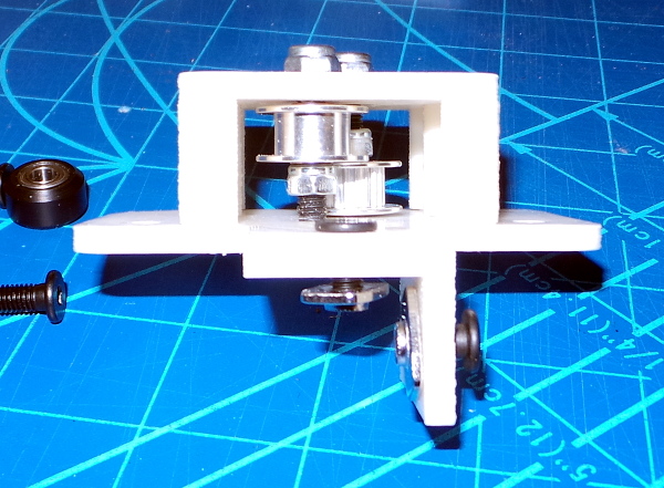
Now assemble the wheels on screws through the bottom carriage piece and join the top and bottom carriages with lock nuts. The bottom carriage pieces are bottom-left-y-carriage.scad
Attach the microswitches to the switch holders and the switch holders to the carriages to act as X home and limit switches (actually you can do this much later but it may be simpler to do it now). The switch holders are right_switch_holder.scad and left_switch_holder.scad
Put 4 10mm screws and t-nuts in the holes where the X rail will be mounted in each Y carriage.
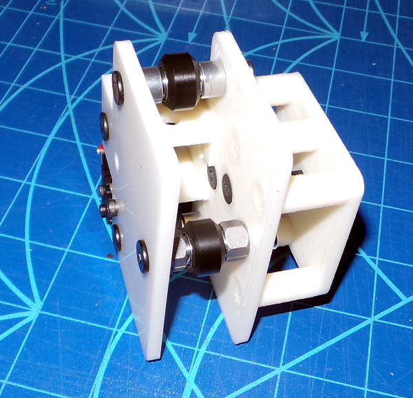
Build the X carriage
Simpler than Y, this just needs the wheel assemblies and the top and bottom go together with lock nuts. You can attach the extruder mount now or later (I already did all this a while back when checking how the parts went together). The parts for this are top-x-carriage.scad (which also includes the wedges and inserts to secure and adjust the belts) and bottom-x-carriage.scad. The e3d_mount.scad is for the hot end mount (and probably fits most common hot ends, not just the e3d).
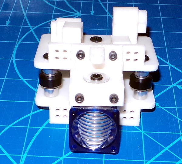
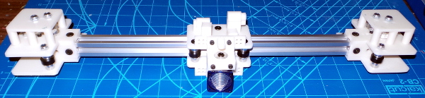
Put together the XY carriage assembly.
Very carefully, push the X rail into the opening with the 4 t-nuts on the left Y carriage (tricky, but once you get things lined up right, you can get the rail inserted into all 4 nuts). Tighten the nuts a little to hold it in place.
Slide the X carriage onto the X rail.
Now, somewhat more carefully since the X carriage is sliding around (best to hold the carriage and rail in one hand while doing the insertion), insert the X rail into the right Y carriage and get the nuts tightened.
Slide a limit switch to the back of the left Y rail. These parts are in ystop.scad. As with the Z limit parts a 10mm screw is too long, use 8mm scres for these.
Slide the left Y carriage onto the left Y rail. Adjust the eccentric spacers till the wheels grip the rail but still turn easily.
Slide on another limit switch on the left Y rail (so we'll notice back and front motion limits).
Slide the right Y carriage onto the right Y rail.
Slide the corner brackets into the bottom of each end of the Y rails and add t-nuts and screws that will attach to the vertical rails. (The corner brackets I'm using are openbuilds parts).
Very carefully, slide the XY carriage assembly down over the vertical rails, engaging the t-nuts on the corner brackets into the slots in the inside of the rails. May need to loosen the nuts holding the X rail to the Y carriages to adjust the width of the complete X-Y assembly so it will fit well.
Put together the front motors and motor brackets.
Screw the motors into the brackets with the M3 screws on the face. The motor mount is xy-motor-mount.scad and is the same part for both left and right motors (so print two).
Add the driver pulleys to the motors (paying attention to the orientation so right hand motor is for driving high belt, left for low).
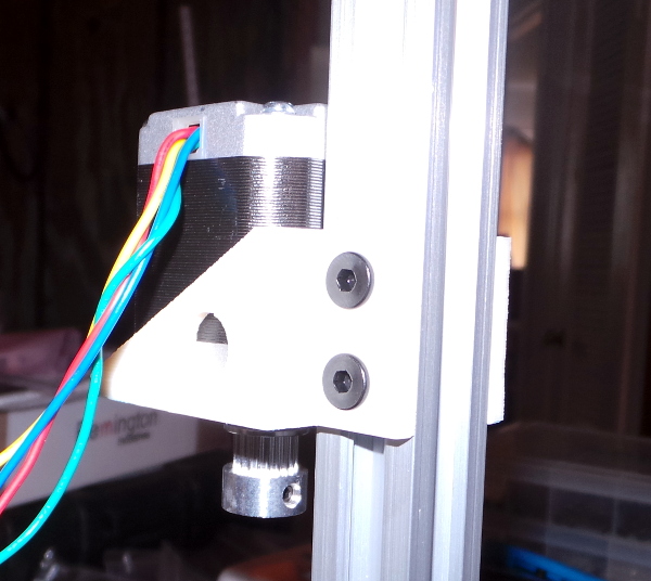
Slide them over the vertical rails with motors facing down.
Put together the stacked pulleys
Put the 10mm M5 screws and t-nuts on the mounting holes first because you can't get them past the pulleys later. Also, I made two holes behind the pulleys, but there just isn't room to get a driver in to tighten the bottom screw, so i left it off. I only use a total of 3 screws and t-nuts to mount these. Due to the slightly different dimensions of the idler pulleys and the drive pulleys, there is a right_stacked_pulley_bracket.scad and a left_stacked_pulley_bracket.scad which look almost identical, so you might want to label them after printing to avoid getting the mixed up.
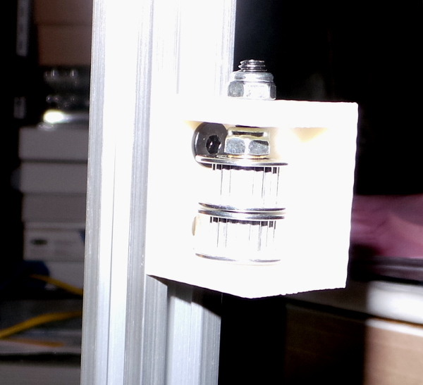
M5 screw through the bottom, brass spacer, pulley, brass spacer, pulley, brass spacer, then there is just enough room to put a lock nut above the top pulley to keep them from moving, then another lock nut on the outside to secure the M5 screw.
Slide the stacked pulleys on to the vertical rails.
Top rails
Slide the bowden extruder on to the left top rail. There are lots of parts to this, shown over in the Extruder page.
An entirely optional feature is the nameplate.scad I slid on the top front rail.
Now add the corner plates to the top rails and attach them.
Now try to get all this nonsense squared up :-).
Move the print bed wheel brackets till they get the wheels in the rails solidly and tighten the nuts. Do any final adjustments using the eccentric spacer. Center the Z motors on each side and tighten the nuts. Run the acme screws through the Z nuts and into the 5mm to 8mm adapters on the Z motors. Slide the Z nut on the print be rail till it is exactly aligned with the Z motor. Slide the left and right print bed rails till it is exactly aligned in the other direction. Tighten the rails and nuts.
Move the XY motors as high as they will go and tighten the nuts.
Move the XY carriage as high as it will go without running into the drive gears. Make sure it is the same height at each corner, tighten the nuts in the corner brackets. If necessary, losen the X rail nuts to get the proper spacing for the Y rails, then tighten them again once the Y rails are fixed.
Position the drive gears on the motors to be the exact same height to match the pulleys in the Y carriages.
Position the stacked pulleys likewise.
Belts
Start one end of the belts in the adjustable belt holder on the X carriage, with the adjuster positioned as far out as possible. Run the belt through the Y carriage, the two stacked pulleys, the other Y carriage and into the fixed position belt holder. Tighten the belt as much as possible by hand. Get both belts run this way, then use the adjustable belt holder to do final tightening.
Smoothieboard
Solder on the 5V regulator and the headers I'll need to use for jumpers to drive the two Z motors in parallel. Also add headers for extra GPIO connections for use with things like the external mosfet circuit I'll need to drive the bed heater and a switch for out of filament detection, etc.
Get the smoothieboard secured to the mount (probably need to turn the printer on the side to get to the bottom where the nuts will need to go).
Decide which connectors to use for what (motors, switches, etc). Hook up gazillions of wires to the smoothieboard. Fiddle the smoothieboard config file on the sdcard to match the connections made. (This is looking like a fairly non-trivial step since the info on configuring the smoothie firmware is somewhat confusing, but I'm sure I can eventually figure it out).
Hook up power to the smoothieboard.
Yikes! Time to start testing! First and most important, verify that the board recognizes all the home and limit switches being hit. Then try moving things.
Misc thoughts
Do I want to design some sort of thing to go in the rails where I can wire tie various cables? Can I make it some sort of clip-in thing I can add later when I know where I want it?
What about some poles between the verticals at top and bottom to run the wires past and keep them out of the way? Or maybe a cable chain or two?
Final bits.
I can run the bowden tube and the wires to the E3D any time (not to mention actually finishing the E3D assembly).
I'll eventually want a PWM cooling fan attached to the X carriage as well, but I can also do that later.
I've got a nice airtight container which I want to rig up with a spool mount inside it, a place for dessicant packs and a hose connector for PTFE tubing to run up to the extruder (thus keeping the entire path sealed against humidity). That can all happen later though.