AardRemote Box
I didn't have any specific plan for the box to hold my AardRemote prototype, so everything has been invented on the fly based on what junk I had laying around or could easily obtain.
I started with a breadboard and gradually evolved to a final form:
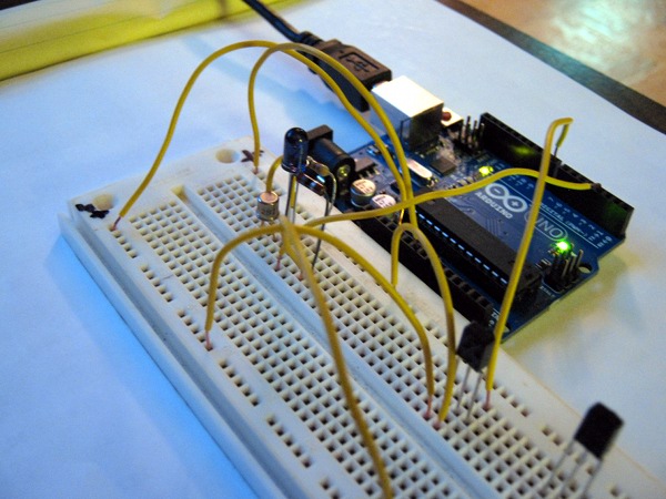
The initial breadboard rig looked like this (bluetooth shield not connected while I'm working on microcode):
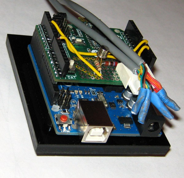
With most of the software working rather well, I finally turned to soldering the components to the prototype area of the bluetooth shield. Only took about 6 hours for me to do this 5 minute job, but one advantage of going so slow and being so careful was that it worked the first time I plugged it in :-).
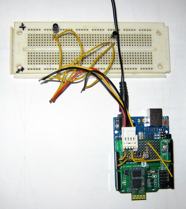
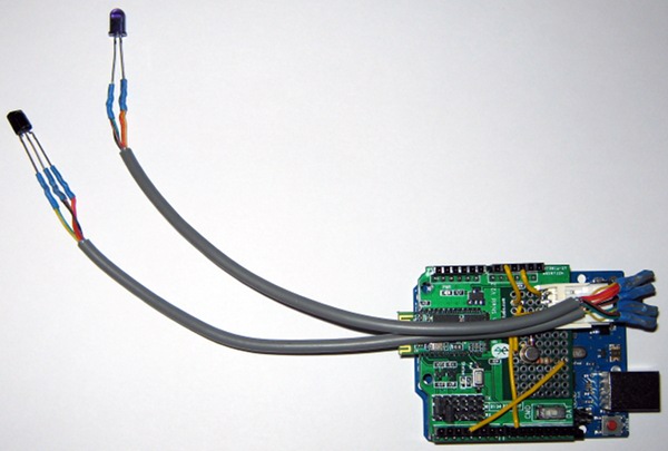
I used a salvaged floppy disk power connector to bring the leads for the IR emitter and receiver off the board so I can run cables to windows in whatever kind of box I eventually decide to put this in, but initially I just ran the cables from the connector to the original breadboard which only has the two IR components on it now.
Here's a cose up of the arduino and shield:
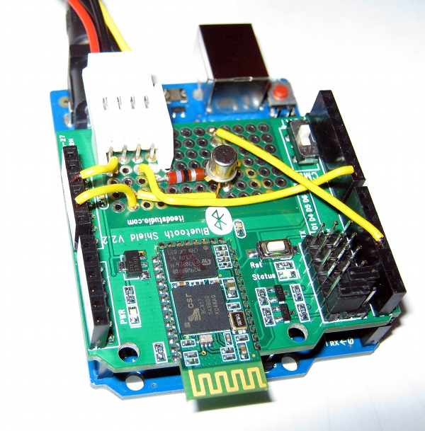
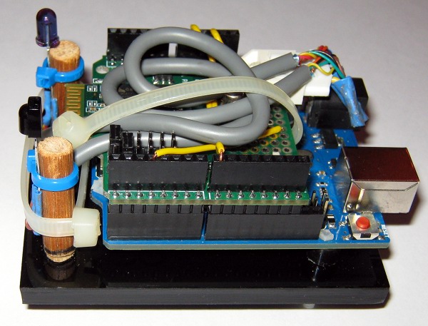
Eventually, I got rid of the breadboard completely and stuck the emitter and receiver on some cables cut from a dead PS/2 mouse:
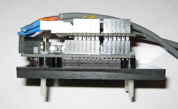
And here's another close up shot:

Now all I need is a 3D printer and a design for an aardvark enclosure to put it in :-).
Lacking a 3D printer, I've started on the physical mounting by cutting a slab off a piece of black plexiglass I had laying around and using a paper template made from the arduino to guide drilling and tapping some holes for nylon mounting screws:
I made some highly sophisticated standoffs by cutting bits off an old Papermate disposable plastic pen that wouldn't write anymore:
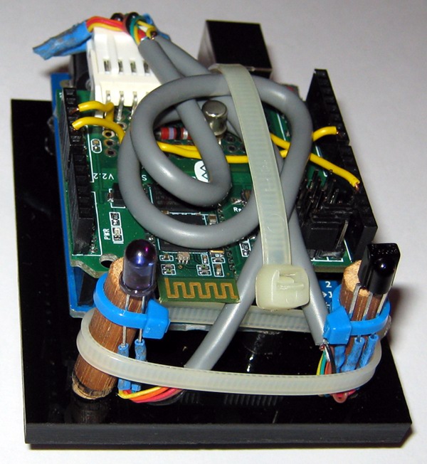
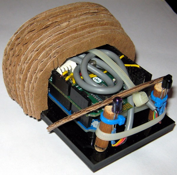
And now I've added a couple of new holes and bits of dowels to tie the LED and IR receiver to:
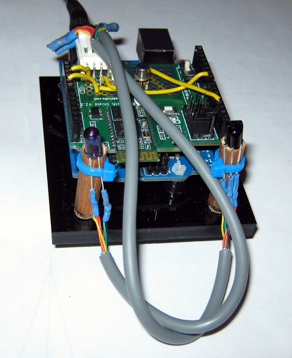
A couple of more wire ties to get everything bound up into a smaller area (and to hold the dowels in place by pulling them together to wedge the base into the holes):
I just need to build a shell to enclose it all now. The plan for that: Cardboard, paper-mache, sanding, paint, and polyurethane (that's the plan now, anyway :-).
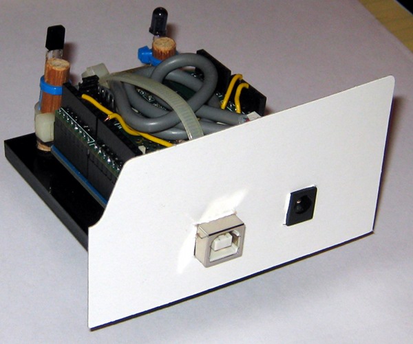
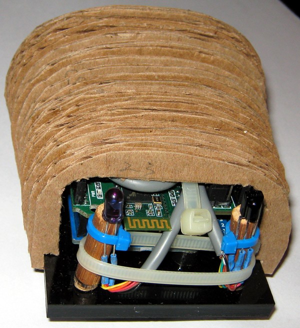
I start with an oversize cardboard back cover with holes for the USB and power connectors:
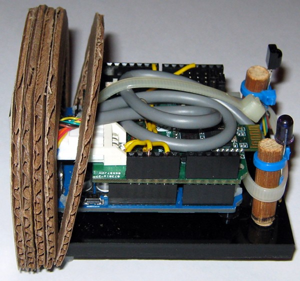
Then glue on a gazillion layers of corrugated cardboard cut to form the shape of the shell:
Once I get all gazillion layers in place it will be time to use the Paper Mache Clay recipe to coat the cardboard with a hard paintable shell.
Meanwhile, the cardboard layers keep growing:
...and the coocoon is almost finished now:
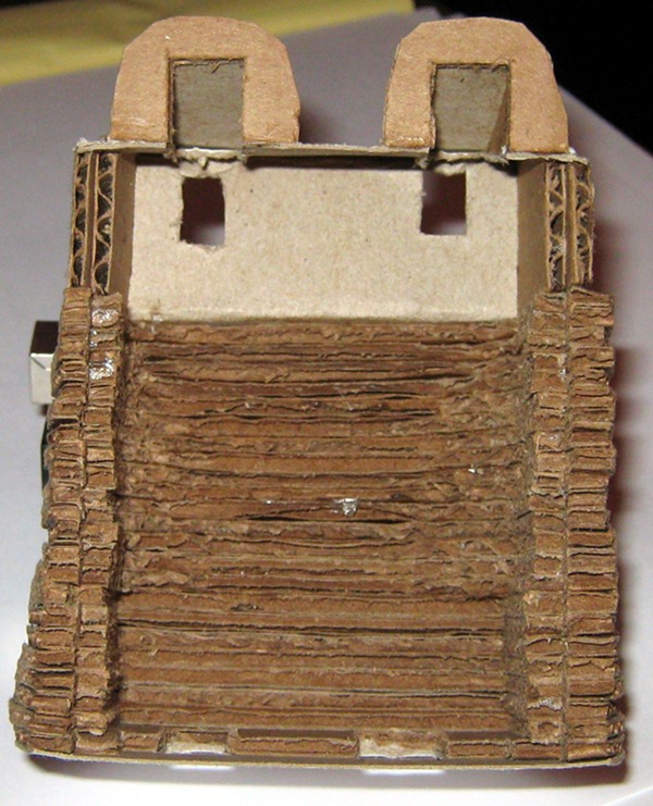
I now have the nose cone in place:
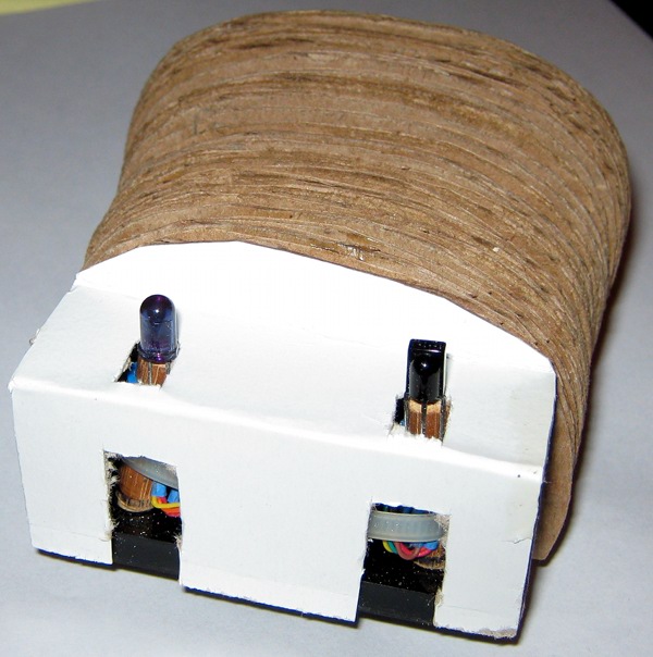
But it still needs a couple of nostrils to allow room for the cover to tilt back and come off:
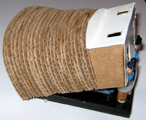
I think I've finished the cardboard part of the shell now:
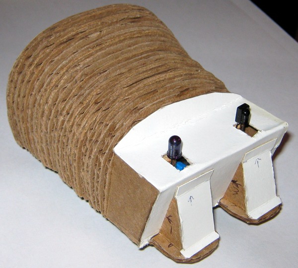
There is enough clearance to tilt the shell off and remove it:
Next stop: Attempting to make paper mache clay and turn the cardboard shell into a hard shell:
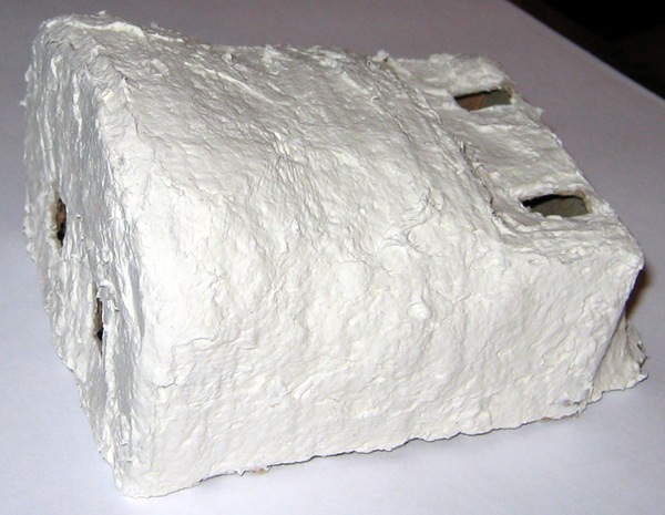
Looks a bit like something a 3 year old might produce (I think I made the clay a little on the too dry side), but I can fit the electronics in, and testing it shows that it does indeed work when in the shell:
Even though I haven't fully finished the prototype yet, I've already started plotting the second system version using the Teensy 2.0 board which, as you can see, is aptly named:
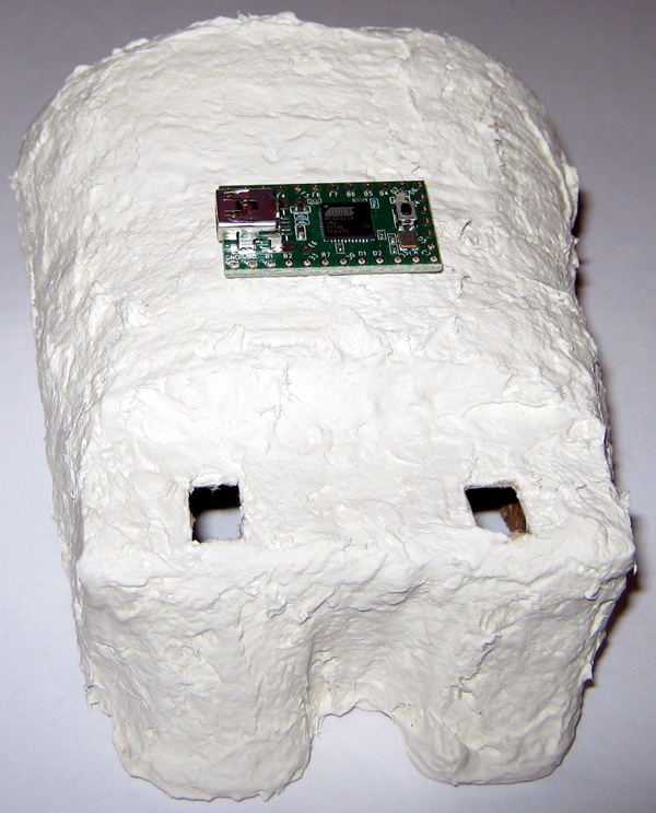
I have a bluetooth serial module on order as well which isn't much bigger than the Teensy board, and I'm imagining them fitting nicely in a small piece of plastic conduit for a case...
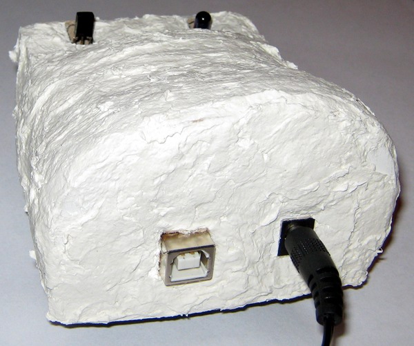
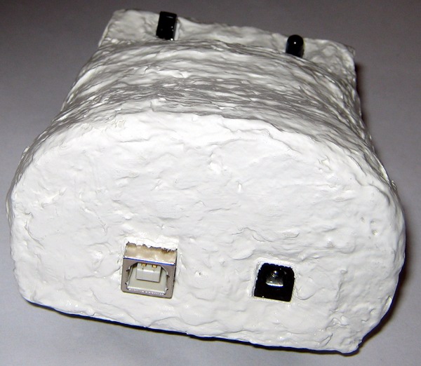
Meanwhile, back on the original case: I haven't quite finished it yet, but I have gotten some paint and clear coating on it, so it is a little whiter and shinier now:
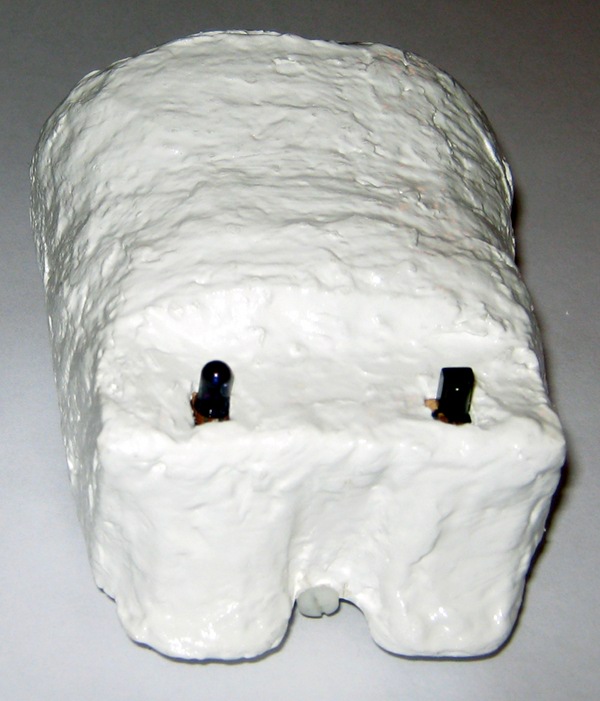
I've also tried running it from various positions around the room, and one obvious conclusion is that the IR LED is not omnidirectional (which it said in the datasheet, but an abstract diagram didn't really convey the real world implications :-). To work reliably from across the room, it pretty much has to have the top end of the LED pointed towards the A/V equipment, so for this case design, that probably means hanging it on the wall by the nostrils (which won't make the learning function very easy to use).
Clearly there is room for improvement here that I should take into account in the 2nd system. I'm already thinking about putting dual LEDs on the ends of stiff wires (like antenna stalks) so they could be individually positioned for maximum effect.
I have left it plugged in overnight inside the case, and it worked just as well in the morning as it did in the evening, so I don't seem to have any heat issues or problems with long term running crashing the code. I don't think I need any more ventilation than the case already has naturally.
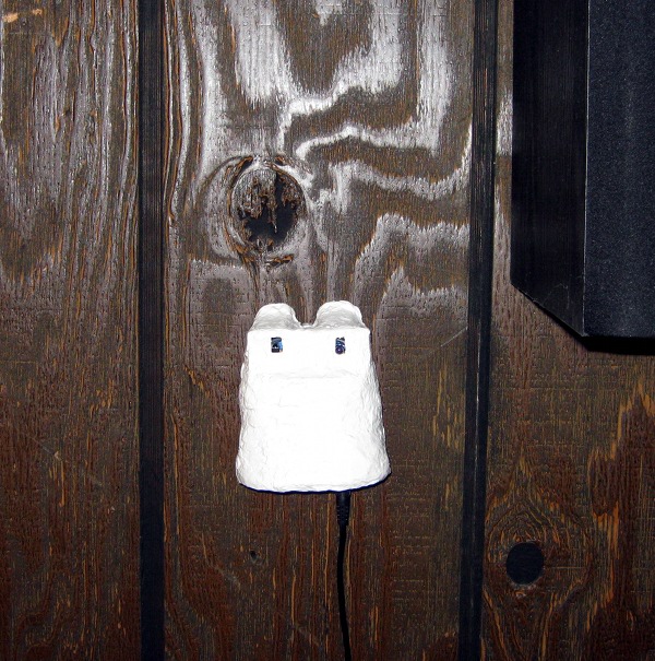
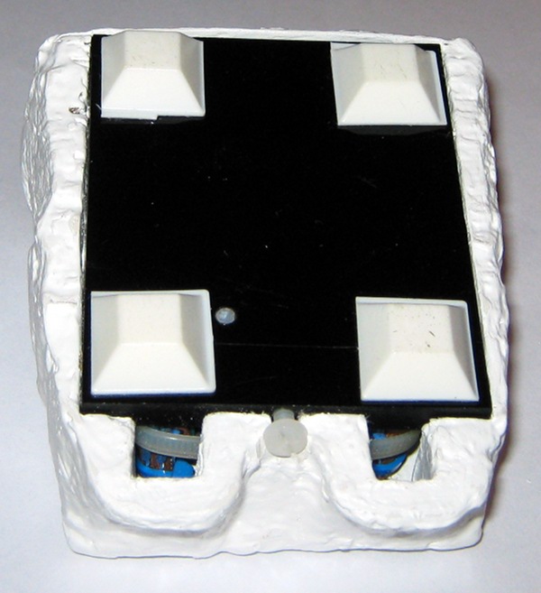
I've now finished the case completely, adding a little screw in a slot to perhaps hold the case on better (not that it wasn't a pretty tight fit anyway):
I've also sliced off the protruding nylon screws and added stick on feet:
And here is what the whole thing looks like on the wall (where it can indeed seem to control everything on the other side of the room):